Differential control topology for LC VCO

a technology of differential control and lc vco, applied in the field of electrical arts, can solve the problems of limiting system performance, noise is an extremely important design concern, and prior art approaches described to date do not implement full differential control

Inactive Publication Date: 2001-09-18
IBM CORP
View PDF3 Cites 81 Cited by
  • Summary
  • Abstract
  • Description
  • Claims
  • Application Information

AI Technical Summary

Problems solved by technology

Noise sensitivity of the components of the PLL can limit the quality of the generated or recovered clock, and may thus limit system performance.
In many PLL applications, and particularly in data communications PLL applications, noise is an extremely important design concern.
The prior art approaches described to date do not implement full differential control.
Furthermore, they do not properly treat the biasing o...

Method used


Image

  • Differential control topology for LC VCO
  • Differential control topology for LC VCO
  • Differential control topology for LC VCO

Examples


Embodiment Construction

Performance of an LC VCO of the present invention was predicted using the well-known SPECTRE circuit simulator. Results are depicted in FIG. 7. The output frequency, f.sub.0 of an inventive LC VCO is shown as a function of a common mode input V.sub.c provided to both input voltage terminals, in curve 701. It will be noted that changes in V.sub.c result in only a minimal change in the output frequency f.sub.0. For comparison purposes, curve 702 depicts a differential mode input over the same voltage range applied to the control inputs. Note the substantial linearity of changes in f.sub.0 with the applied differential mode input V.sub.d. The values for f.sub.0 are in GHz, while those for V.sub.c and V.sub.d are in mV.

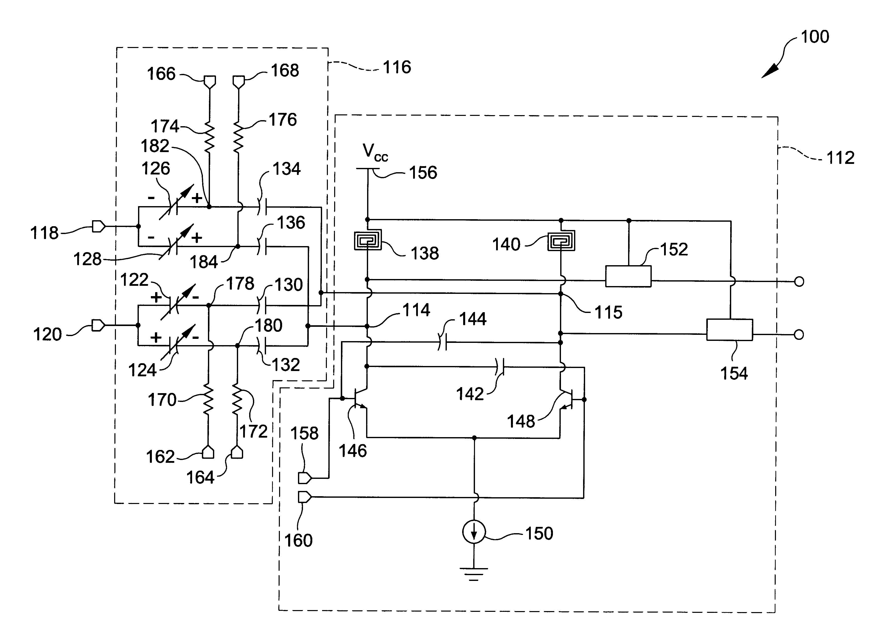
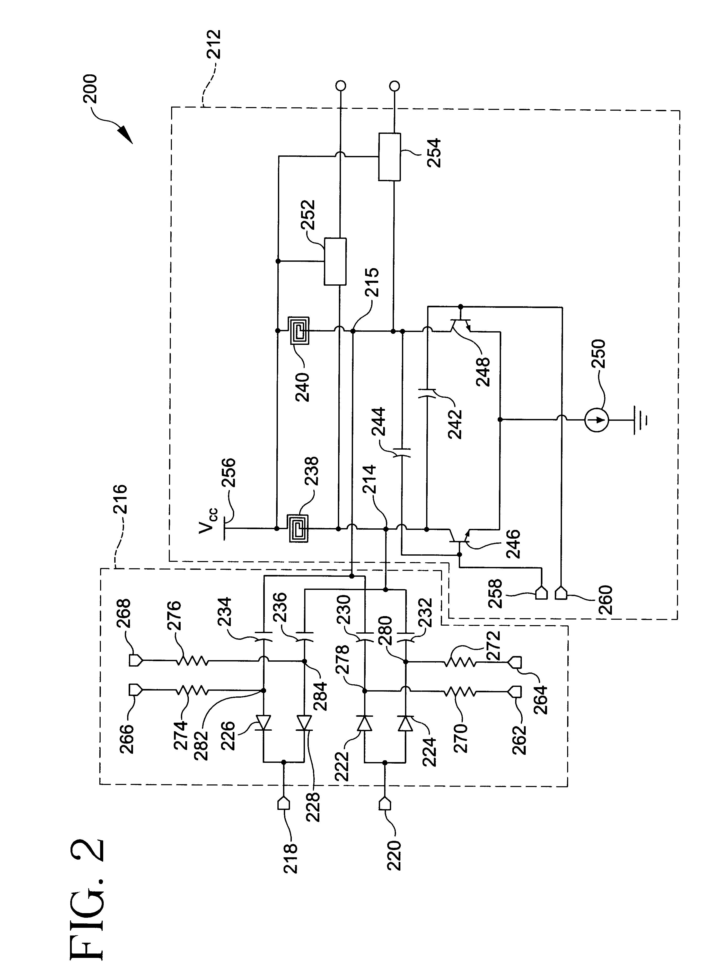
The curves in FIG. 7 can be generated, for example, for the embodiment depicted in FIG. 2, using the following values. The exemplary values are for operation at a nominal frequency f.sub.0 of 12.5 GHz. Nodes 256, 262 and 264 can have an applied DC bias voltage of 3.3 volt...


PUM


Abstract

The LC VCO includes an LC oscillator module with first and second tank nodes and a control module with positive and negative input voltage terminals. The control module includes four voltage dependent capacitive elements which are configured to be biased for operation as voltage dependent variable capacitances. The voltage dependent capacitive elements are interconnected such that the effect of a common mode input voltage is to increase the capacitance of two of the voltage dependent capacitive elements, while simultaneously decreasing the capacitance of two of the other voltage dependent capacitive elements by a substantially similar amount, such that a differential voltage applied across the positive and negative input voltage terminals is operable to change the capacitance of the voltage dependent capacitive elements, and thereby the frequency of the LC oscillator module, while effects on the output frequency of the oscillator caused by a common mode voltage tend to cancel. Accordingly, a fully differential signal path in phase locked loops employing LC oscillators, with improved noise rejection, substantial suppression of common mode noise, and a minimal increase in complexity over a single-ended control design can be achieved. Additional supply voltages need not be employed.

Description

1. Field of the InventionThe present invention relates to the electronic arts, and more particularly relates to a voltage controlled oscillator suitable for phase locked loop circuits such as may be employed in a high speed data communication link.2. Brief Description of the Prior ArtPhase locked loops are important in the field of high speed data communication. They are employed in clock multiplier circuits, in which one or more high frequency output clocks are synthesized from a reference input. They are also used in clock and data recovery (CDR) circuits, in which the clock and data are recovered from a single high-speed serial stream of non-return to zero (NRZ) data. In systems which employ phase locked loop (PLL) circuits, the precision of the generated or recovered clock is critical to the performance of the system. Noise sensitivity of the components of the PLL can limit the quality of the generated or recovered clock, and may thus limit system performance. Clock multiplier c...

Claims


Application Information

Patent Timeline
IPC IPC(8): H03B5/12H03B5/08
CPCH03L7/099H03B5/1253H03B5/1215H03B5/1231
Inventor FRIEDMAN, DANIEL JOSEPHMEGHELLI, MOUNIR
Owner IBM CORP
Why Eureka
Try Eureka