Method and apparatus for optimizing heat transfer in a tube and shell heat exchanger

a heat exchanger and tube technology, applied in the field of heat exchangers, can solve the problems of copper heat transfer tubes, costing a lot of fabrication, and limited use of such heat exchangers as water heaters

Inactive Publication Date: 2001-09-25
AQUACAL
View PDF10 Cites 60 Cited by
  • Summary
  • Abstract
  • Description
  • Claims
  • Application Information

AI Technical Summary

Problems solved by technology

In such a device, no control over the flow of water is provided within the internal chamber of the tank and because the heat exchanger incorporates an electrically resistive heating element as opposed to a fluid heat transfer medium, the application of such a heat exchanger is limited to use as a heater for water.
Such a construction, although embodying a simple arrangement of parts, is costly as to fabrication.
There are disadvantages associated with a copper heat transfer tube in a heat exchanger for water.
One example of such disadvantages is in the thermal conditioning of salt water for applications such as holding tanks and aquariums for marine life.
The marine life is susceptible to a toxic reaction to chemically produce products of corrosive reaction between the salt water and the copper metal of the heat transfer tube.
However, to be economically competitive the high cost of titanium metals as compared with the cost of copper or copper-nickel alloy poses a need to reduce the length of heat exchanged tubing.

Method used


Image

  • Method and apparatus for optimizing heat transfer in a tube and shell heat exchanger
  • Method and apparatus for optimizing heat transfer in a tube and shell heat exchanger
  • Method and apparatus for optimizing heat transfer in a tube and shell heat exchanger

Examples


Embodiment Construction

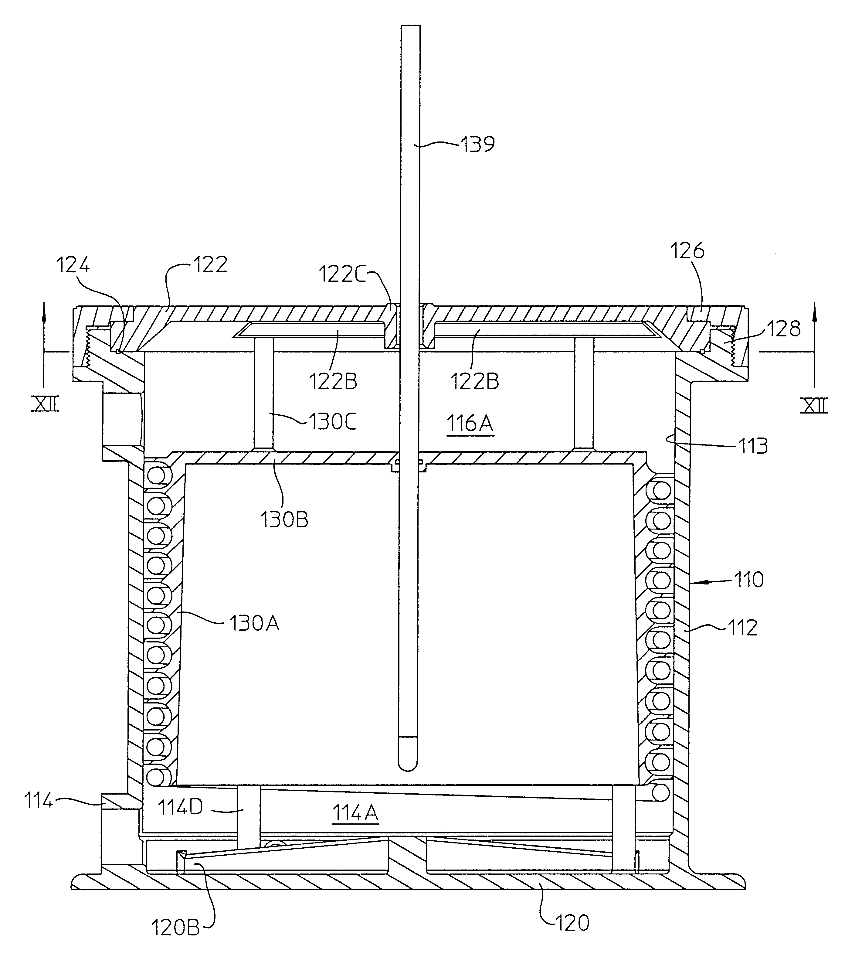
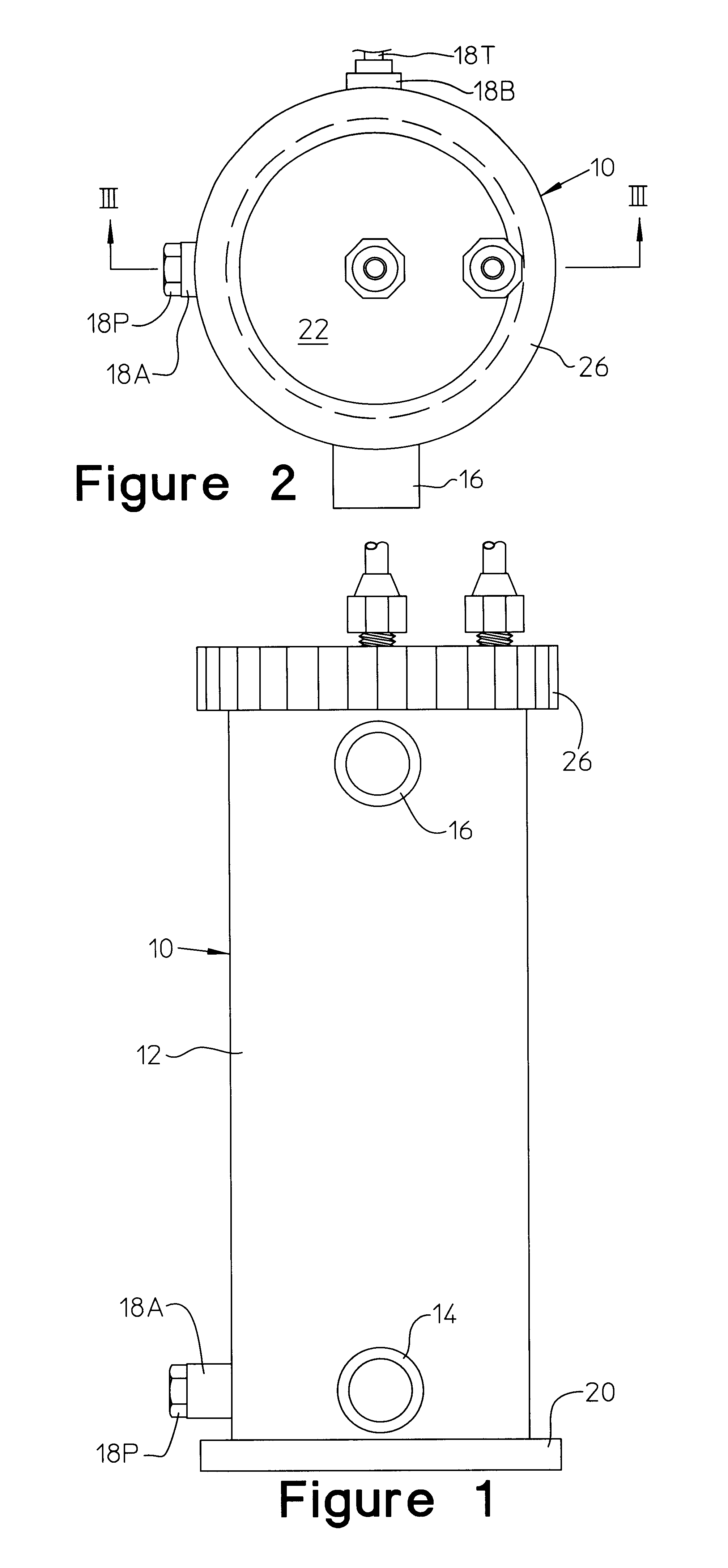
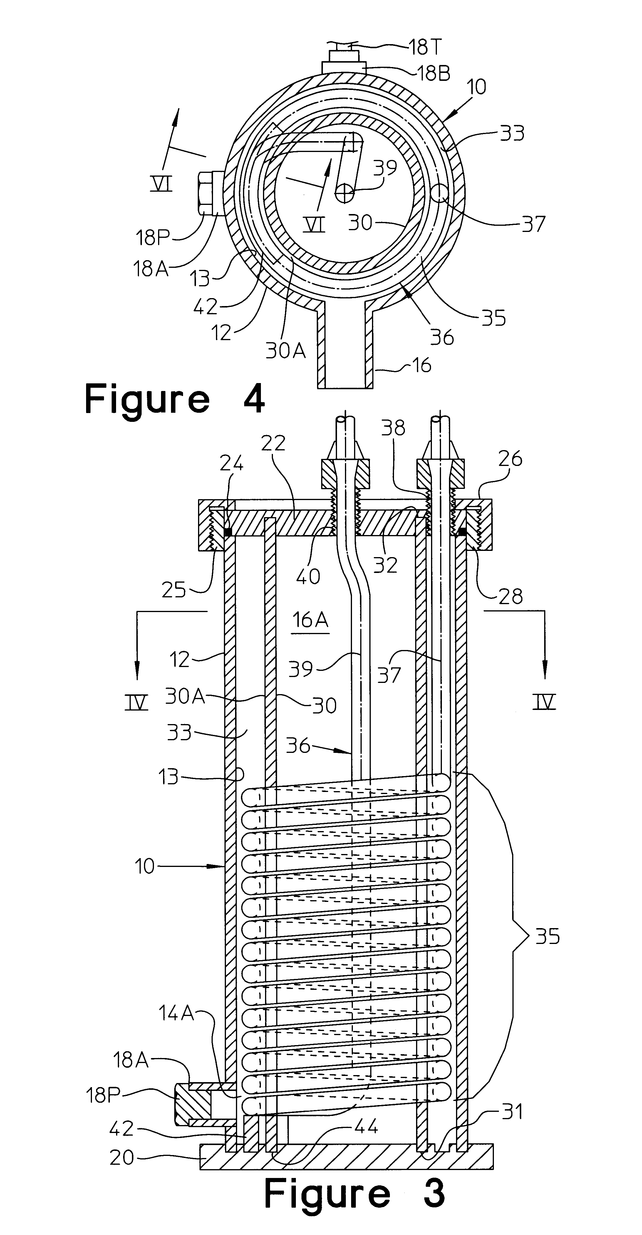
Referring to FIGS. 1-4, there is shown a first embodiment of a heat exchanger 10 embodying a construction and the arrangement of parts useful to form an evaporator unit or condenser unit for diverse applications including water heaters, water coolers particularly, for swimming pool water of swimming pools, spas, aquariums (both fresh and salt water), a heat exchanger for marine engines and heat pumps. The heat exchanger includes a cylindrical outer shell 12 providing a cylindrical internal face surface 13. The shell 12 has a fluid inlet port 14 located adjacent the bottom of the shell through which a first fluid medium such as water is introduced into a supply chamber 14A of the heat exchanger and a fluid outlet port 16 located adjacent a discharge chamber 16A at the top of the shell from which the water exits the heat exchanger. The fluid inlet port 14 and fluid outlet port 16 each have a central axis oriented to extend radially and intersecting with a central longitudinal axis of ...


PUM


Abstract

A tube and shell heat exchanger having a transversely oriented inlet port and a spirally coiled heat transfer tube contained within an arcuate chamber created by an internal baffle in which the water to be conditioned travels along a helical pathway in which the flow has minimized water depth and high turbulence. The tube and shell heat exchanger maximizes heat transfer capability in a relatively easy to assemble design to make feasible the use of a higher cost material for the tubing such as titanium in a wide range of applications.

Description

1. Field of the Invention: The present invention relates to a heat exchanger for thermal conditioning of one fluid medium by heat transfer with a second fluid medium in a heat transfer tube and, more particularly, to a method and apparatus for enhancing heat transfer between the flow of one heat transfer medium and a different heat transfer medium in an evaporator unit or condenser unit for diverse applications of heat transfer including water heaters and water coolers particularly, for water of swimming pools, spas, aquariums (both fresh and salt water) and as a heat exchanger for marine engines and in heat pumps.2. Description of the Prior Art: Evaporator and condenser functions provided by a heat exchanger are commonly used for diverse applications and while not so limited, the present invention is particularly useful in one common field of used where heat transfer with one medium consists of a flow of water for a swimming pool or spa. Swimming pool water is heated or cooled depe...

Claims


Application Information

Patent Timeline
Patent Type & Authority Patents(United States)
IPC IPC(8): F28F13/12F28F13/00F28D7/00F28D7/02
CPCF28D7/022F28F13/12F28D7/024
Inventor TAWNEY, JEFFREYDENORCY, DAVODSMITH, DAVEPATRICK, MICHAEL
Owner AQUACAL
Why Eureka
Try Eureka