System to determine solenoid position and flux without drift

a solenoid position and flux technology, applied in the direction of motor/generator/converter stopper, dynamo-electric converter control, magnetic body, etc., can solve the problems of increasing cost and complexity, and affecting the operation of solenoid position and flux, so as to reduce hardware/software and high frequency energy

Inactive Publication Date: 2001-10-09
BERGSTROM GARY E
View PDF14 Cites 19 Cited by
  • Summary
  • Abstract
  • Description
  • Claims
  • Application Information

AI Technical Summary

Problems solved by technology

Some systems add a position sensor, which increases the cost and complexity.
But a problem in all of the systems that measure flux by doing an integration, such as Gingrich's, is that over time the integral will drift.
But many valves and solenoids must hold a driven position for long periods of time, and cannot rely upon the chance that they will move to a known boundary condition and allow the integrator to be corrected within the short period of time that drift remains a small error.
The constant current drive method has errors relating to the lack of any feedback, and the inductance measurement technique has been hampered with noise and measurement accuracy problems.

Method used


Image

  • System to determine solenoid position and flux without drift
  • System to determine solenoid position and flux without drift
  • System to determine solenoid position and flux without drift

Examples


Embodiment Construction

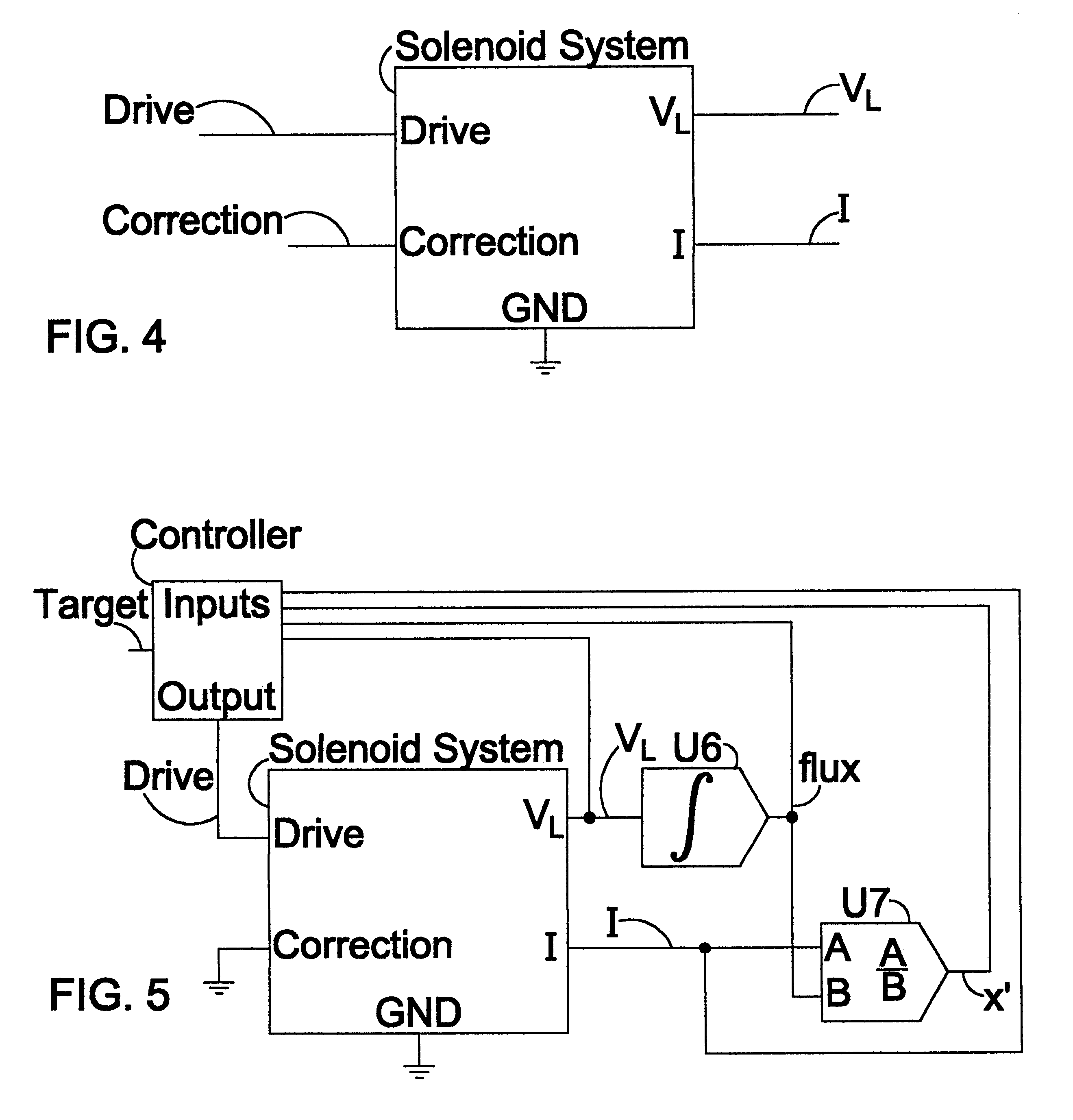
The simple closed loop feedback system of FIG. 5 can be adequate in many applications. The basic method of controlling flux in the solenoid core and computing position from the current and flux signals has been described. As mentioned, this system suffers from drift in the computation of the flux signal. This computation may either be in analog or digital hardware, or it could be completely contained in the software of the Control system. In any case, it is not possible to integrate the inductive voltage V.sub.L over indefinite periods of time without an error.

Some possible error sources are:

offset voltage in an analog integrator (e.g. U6 in FIG. 5)

a / d error (gain, offset, truncation) in measuring V.sub.L

a / d error (gain, offset, truncation) in measuring I, when used to compute V.sub.L

noise

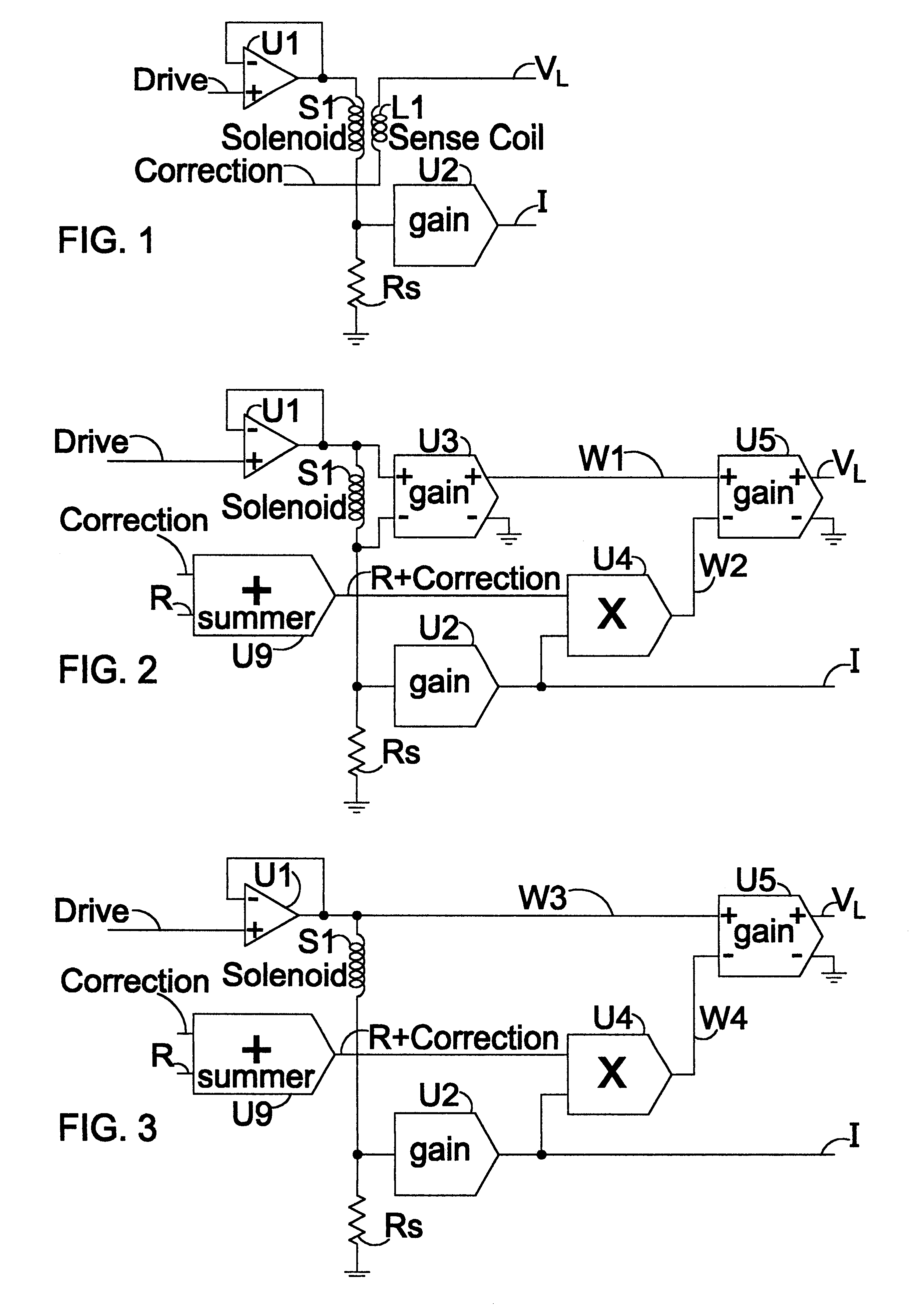
Drift in the integrator in FIGS. 2 and 3 can be modeled accurately enough as an error in the value of the resistance (R.sub.L) of the coil. To correct drift, one just needs to correct the value of ...


PUM

PropertyMeasurementUnit
frequenciesaaaaaaaaaa
drive voltageaaaaaaaaaa
currentaaaaaaaaaa

Abstract

A system for measuring and controlling solenoid armature position. The system determines inductive voltage in the drive winding of the solenoid, integrates that voltage to obtain flux, and uses the current / flux ratio to measure armature position. To overcome integration drift, the current / flux position measure is compared to an independent position measure, this comparison leading to a drift correction. In an embodiment maintaining a servo-controlled position, flux drift causes position drift and current drift, the latter providing an independent measure of position drift and flux drift, permitting drift correction. In a second embodiment, a high frequency component of the drive voltage (possibly from pulse width modulation) and a high frequency current measurement provide the independent measure of position.

Description

1. Field of the InventionThis invention relates to correcting the drift associated with the determination of position and flux in variable reluctance devices such as solenoids. This drift is present in systems that integrate a measured parameter of the device in order to determine flux and position.2. Description of the Prior ArtThe prior art related to the present invention includes many techniques to determine the position of a solenoid. Some systems add a position sensor, which increases the cost and complexity. Others have attempted to infer position from signals that either exist on the system or are cheaper to generate than including a position sensor. Jayawant (U.S. Pat. NO. 5,467,244) describes a measurement system that balances the position of a solenoid. Stupak (U.S. Pat. No. 4,659,969) uses a Hall sensor to measure flux. Gingrich (U.S. Pat. No. 4,368,501) shows how to generate flux (.PHI.) from a second winding. The desirability of flux information comes from the approxim...

Claims


Application Information

Patent Timeline
Patent Type & Authority Patents(United States)
IPC IPC(8): H01F7/18H01F7/08
CPCH01F7/1844H01F2007/1861H01H2047/046
Inventor BERGSTROM, GARY E.
Owner BERGSTROM GARY E
Why Eureka
Try Eureka