Laser controlled flame stabilization

a technology of flame stabilization and laser control, which is applied in the direction of burner control devices, combustion types, lighting and heating apparatus, etc., can solve the problems of inability to sustain flames and unstable combustion processes

Inactive Publication Date: 2001-10-16
LOS ALAMOS NATIONAL SECURITY
View PDF9 Cites 20 Cited by
  • Summary
  • Abstract
  • Description
  • Claims
  • Application Information

AI Technical Summary

Problems solved by technology

However, when lean fuel mixtures are used, the use of a pilot light with a richer fuel / air mixture is necessitated to stabilize the flame because otherwise, at fuel / air composition mixtures near the flammability limit, the combustion process becomes so unstable that the flame cannot be sustained.

Method used


Image

  • Laser controlled flame stabilization
  • Laser controlled flame stabilization
  • Laser controlled flame stabilization

Examples


examples

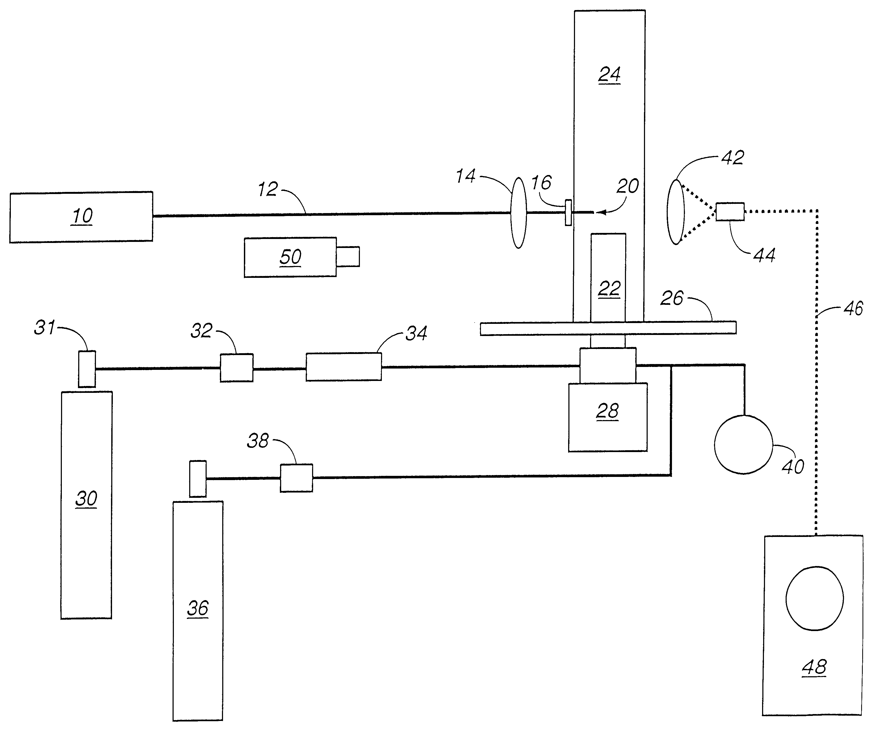
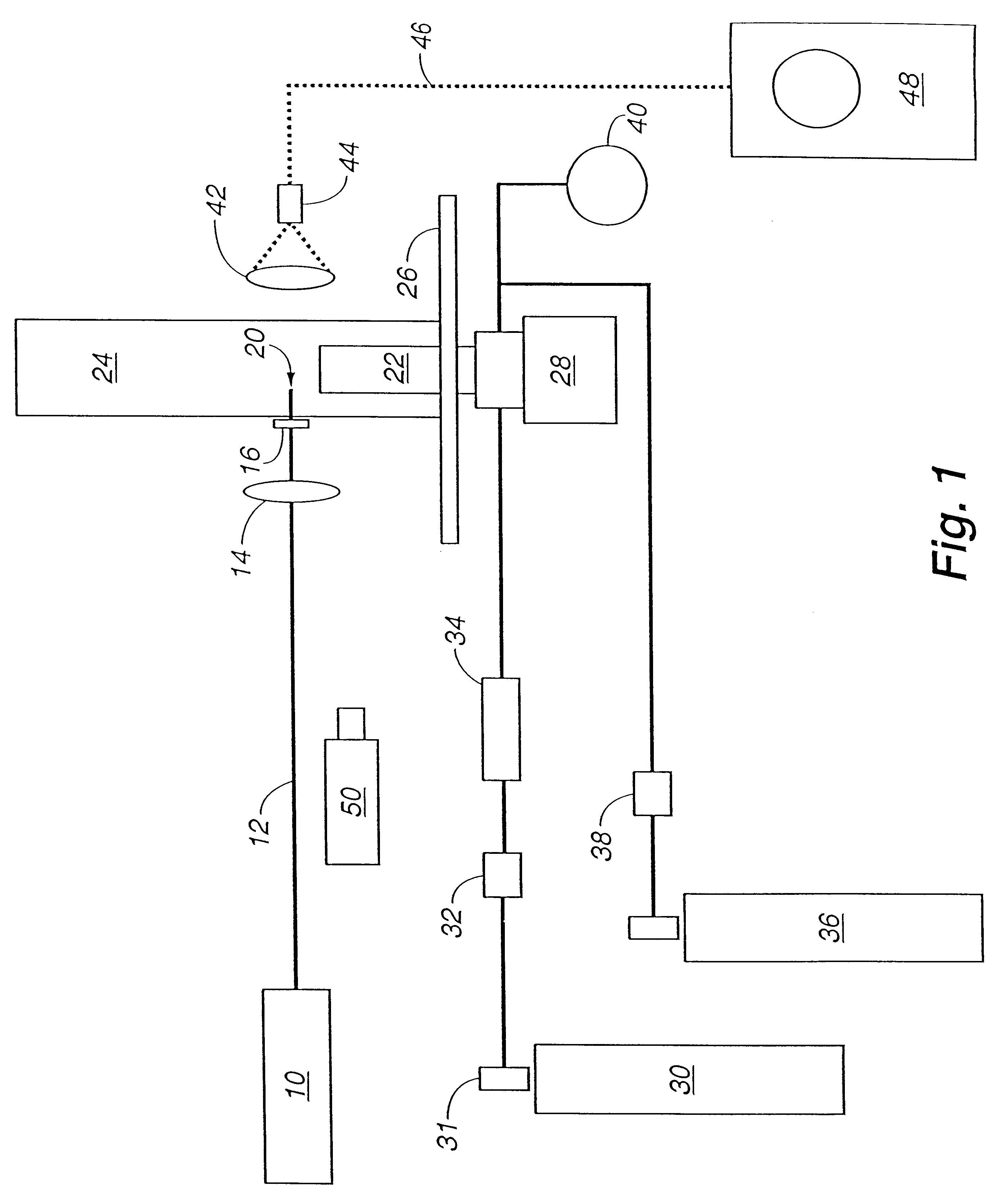
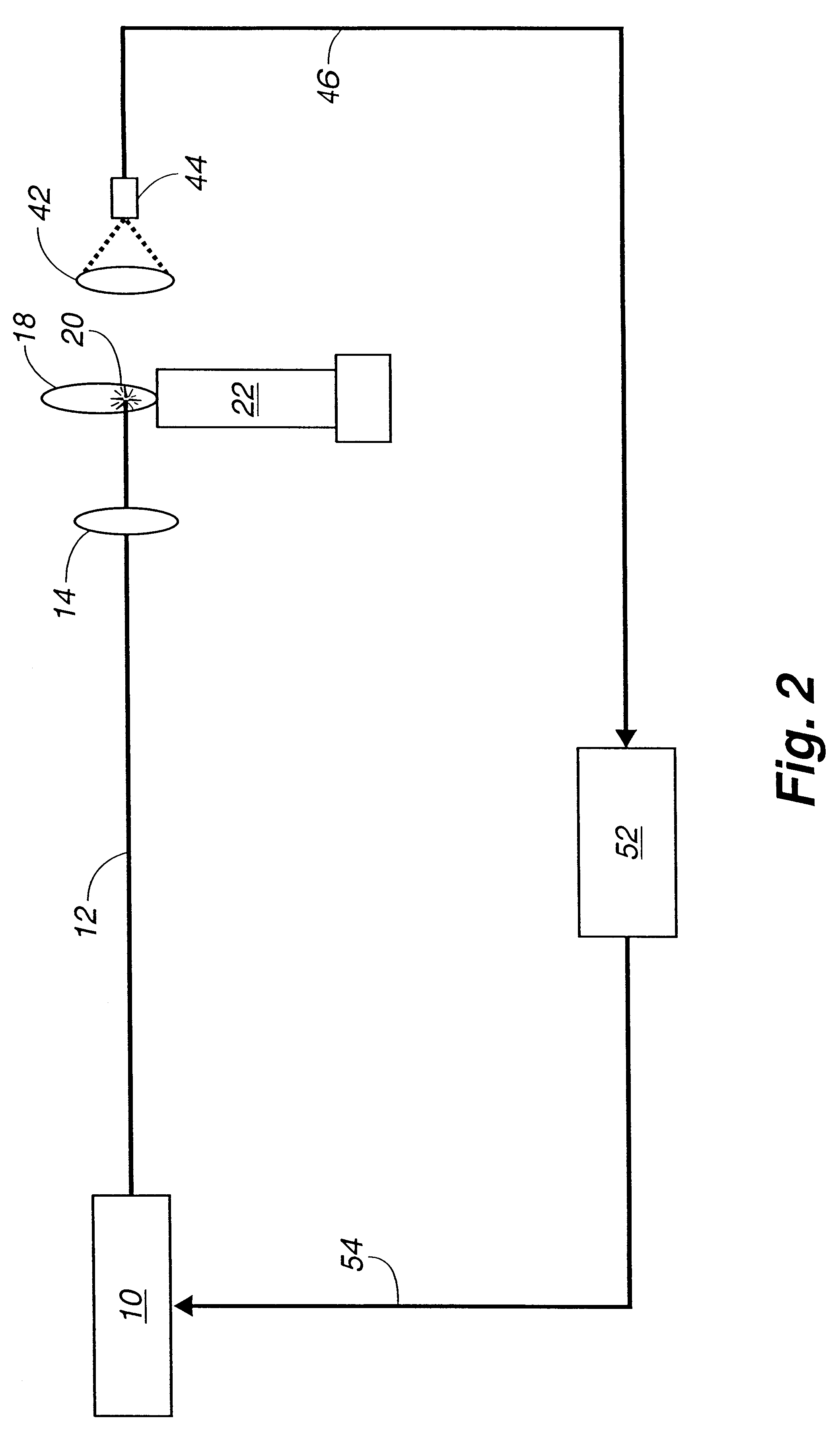
The following examples will demonstrate the operability of the invention. In the following examples, a series of test runs were made to determine the ability of a laser generated air breakdown spark to stabilize the lean burn combustion of methane / air mixtures in accordance with the invention. Flame stabilization was characterized as a function of methane / air mixture composition, total gas flow rate, laser pulse repetition frequency and laser spark location within the combustible gas flow. In Examples IV and V, performance of the invention method was compared directly with performance of a continuous pilot flame of the kind typically used for the selected conditions.

In each of the examples, a swirl injected natural gas nozzle designed and fabricated by CFD was used for fuel introduction. The swirl injected natural gas nozzle was a 1 / 20-scale version of an injector used for commercial electric power turbines.

A Q-switched Nd:YAG laser, pressure and flow monitoring instrumentation, equ...

example i

A set of 12 runs was made to investigate the lean blowout limit for various flows of methane and air with and without the presence of the laser spark stabilization.

The laser was operated at an output pulse energy of 95 mJ and at a repetition rate of either 1 or 3 Hz. The spark generated by the focused laser light was positioned about 3 mm above the top of the nozzle and at the middle of the annular area of the nozzle output, thus permitting recirculation of the lean fuel / air mixture.

In the 12 runs of this example, the combustion tube was placed over the nozzle and oriented so that the tube window was centered upon the focused laser light. Also, the air holes below the nozzle were closed to prevent the entrainment of outside air.

Fuel was introduced to the nozzle and ignited by applying a laser spark. The laser light was then blocked and air flow to the nozzle was established. Air flow was then adjusted to the desired .DELTA.P and maintained at that setting. With the laser off, the fl...

example ii

A second set of runs were made in a manner identical to that described above for Runs 1 through 12 with the exception of the addition of entrained air obtained by opening in the combustion tube below the nozzle.

About the same results were obtained as in the first series of runs with approximately a 5% difference between invention stabilized and comparison unstabilized output limits. In each of these runs, a considerable flicker in the light output of the flame was observed near the extinction limit under both the laser stabilized and free burn conditions.


PUM


Abstract

A method and apparatus is provided for initiating and stabilizing fuel combustion in applications such as gas turbine electrical power generating engines and jet turbine engines where it is desired to burn lean fuel / air mixtures which produce lower amounts of NOx. A laser induced spark is propagated at a distance from the fuel nozzle with the laser ignitor being remotely located from the high temperature environment of the combustion chamber. A laser initiating spark generated by focusing high peak power laser light to a sufficiently tight laser spot within the fuel to cause the ionization of air and fuel into a plasma is unobtrusive to the flow dynamics of the combustion chamber of a fuel injector, thereby facilitating whatever advantage can be taken of flow dynamics in the design of the fuel injector.

Description

This invention relates to use of laser technology for hydrocarbon fuel combustion.Natural gas burning power sources such as gas turbine electrical power generating plants are operated with as lean fuel / air mixtures as practical in order to reduce the production of NO.sub.x emissions. Conventional pilot light flames which burn rich fuel / air mixtures and electrical spark plugs have been used for initiating and stabilizing flames in gas burning turbines. However, when lean fuel mixtures are used, the use of a pilot light with a richer fuel / air mixture is necessitated to stabilize the flame because otherwise, at fuel / air composition mixtures near the flammability limit, the combustion process becomes so unstable that the flame cannot be sustained. The richer burn of the pilot flame itself produces a higher flame temperature which contributes significantly to the over-all production of NO.sub.X.Therefore, a method which does not contribute to NO.sub.x pollutant emissions is needed by the...

Claims


Application Information

Patent Timeline
Patent Type & Authority Patents(United States)
IPC IPC(8): F02P23/00F02P23/04F23C99/00F23N5/16F23N5/08
CPCF02P23/04F23C99/001F23N5/082F23N5/16F23C2900/99003F23D2208/10F23D2209/20F23N2041/20Y02T50/677F23N2241/20Y02T50/60
Inventor EARLY, JAMES W.THOMAS, MATTHEW E.
Owner LOS ALAMOS NATIONAL SECURITY
Why Eureka
Try Eureka