Hardware for high strength fastening of bone

a high-strength, bone technology, applied in the field of surgical fastening hardware, can solve the problems of large force required to prevent excessive motion, affecting the stability of bone, so as to achieve the effect of enhancing strength, determining more accurately the fastening force, and high strength

Inactive Publication Date: 2001-10-16
ACUMED
View PDF8 Cites 213 Cited by
  • Summary
  • Abstract
  • Description
  • Claims
  • Application Information

AI Technical Summary

Benefits of technology

Accordingly, several objects and advantages of the present invention are:
a) To provide a high strength fastener that does not depend upon the strength of the bone being fastened;
b) To provide a fastener with a head on each end;
c) To provide a fastener that passes through both cortical walls with a smooth full size section to further enhance strength;
d) To provide a fastener that may be installed with minimal invasion;
h) To provide a fastener that has a dependable, predetermined torque required to screw it together, therefore enabling the surgeon to determine more accurately the fastening forces being generated by the fastener upon the bone.

Problems solved by technology

The force required to prevent excessive motion is often great.
Such great forces may lead to a problem.
Fastener forces can cause bone damage if the force is generally too high or if it is concentrated over too small an area, causing what may be called "point loading".
Cancellous bone is somewhat spongy, due to physical design.
Open fractures were virtually always fatal.
Such fractures may occur when the hoop strength of the bone is exceeded, such as is generated when an object is driven into the medullary canal with so much force that it splits the bone outward.
Besides the limited strength of wire fixation, a further problem with this general type of fastening, called "cerclage wiring", is that it requires more surgical invasion and periosteal stripping than other methods of fastening.
Smooth pins are sometimes used for fastening bones, but this is typically for low strength requirements and temporary fixation.
Limitations with IM Nailing are that the installation requires additional major surgery, the rods prevent the bone from receiving strengthening exercise, and this "stress shielding" leads to bone weakening.
The strength limitation encountered in fastening with bone screws is at least in part a function of physical properties of bones.
The high-density portion of bone, the cortical bone, is of variable strength; therefore in many cases bone does not provide very good anchoring for threaded fasteners.
With advancing age, the reduction of cortical bone mass with the increase of cancellous bone mass reduces the ability of the patient's bone to anchor threaded fasteners.
When the forces upon the bone (and thus the fastener) are great, the hoop strength and / or shear strength of the bone is exceeded, and the fastening fails (it pulls out allowing the bone fragments to separate)--catastrophically.
A further disadvantage of bone screws which anchor into bone is the high and indeterminate torque of installation.
A surgeon is never certain that the torque he is providing is tightening the bone fragments together (closing the fracture) or merely overcoming the torque required to drive the fastener further into the cortical bone.
1) The cut destroys the thread profile, making disassembly and re-assembly of the bolt and nut difficult or impossible.
2) The cutting action imparts a force couple to the bolt, transmitting unacceptable forces to the surrounding bone.
3) The sharp edge remaining from the pinching off is harsh on the soft tissues, causing pain and trauma.
4) If this sharp edge is filed off, the debris is unacceptable to the body.
A further disadvantage of the nut and bolt fastener is that the threads of the bolt pass unprotected through the cortical bone, and these unprotected threads are free to dig into the cortical bone, creating stress risers that can lead to failure.
A further disadvantage of the nut and bolt fastener is that the washers were flat and fit flat against the bolt head and the nut.
Another disadvantage of this type of bolt and nut is that it was not cannulated.
It could not be installed over a guide wire.
Yet another disadvantage of this nut and bolt is found in the installation tooling.
The nut and bolt fastener could not be rigidly coupled to the installation tool.
A surgeon could not readily insert the fastener accurately into a deep hole, and then direct it unerringly laterally and / or angularly.
At the time of removal, the surgeon could not easily grasp the bolt or nut down deep in soft tissue and pull it from the bone.

Method used


Image

  • Hardware for high strength fastening of bone
  • Hardware for high strength fastening of bone
  • Hardware for high strength fastening of bone

Examples


Embodiment Construction

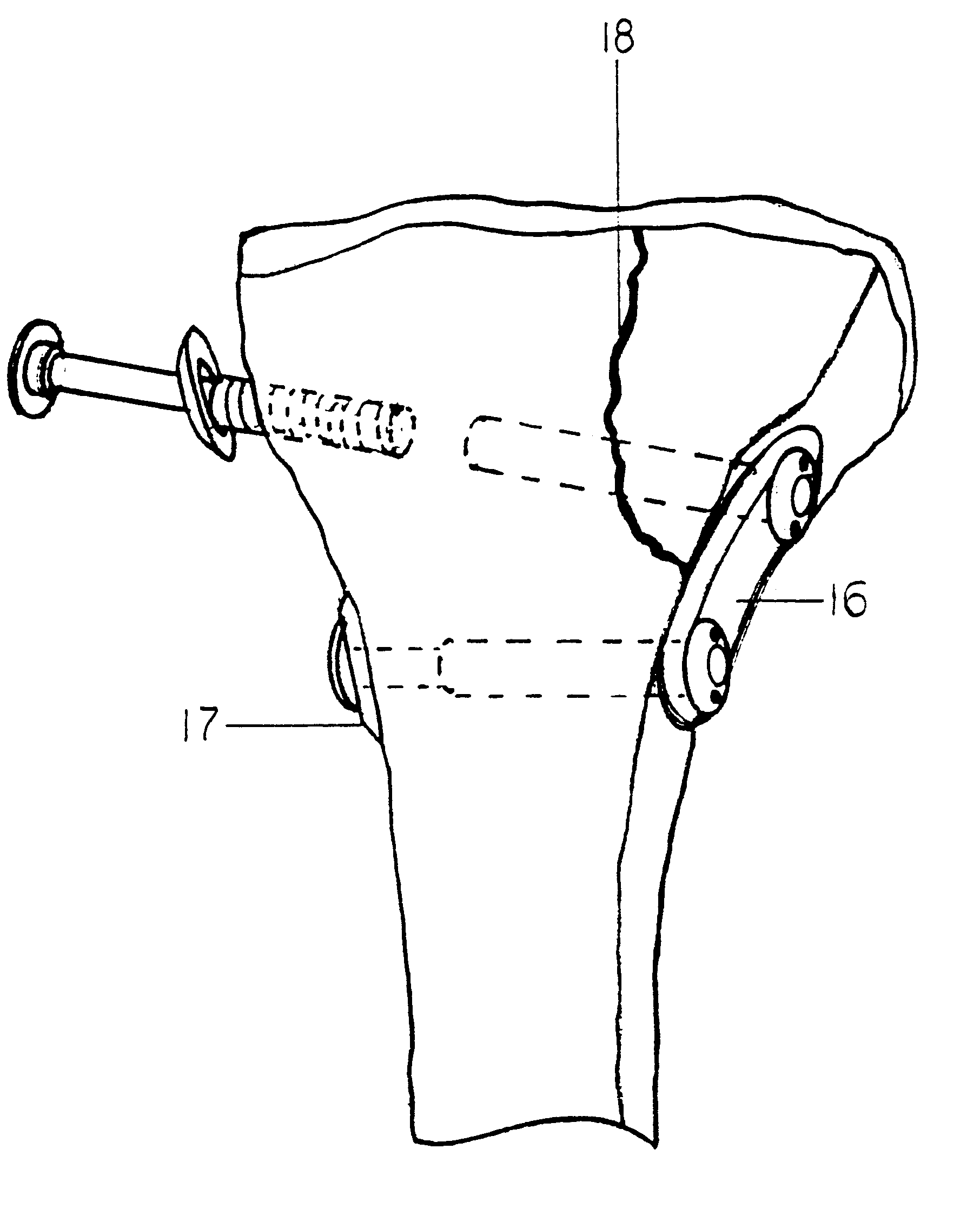
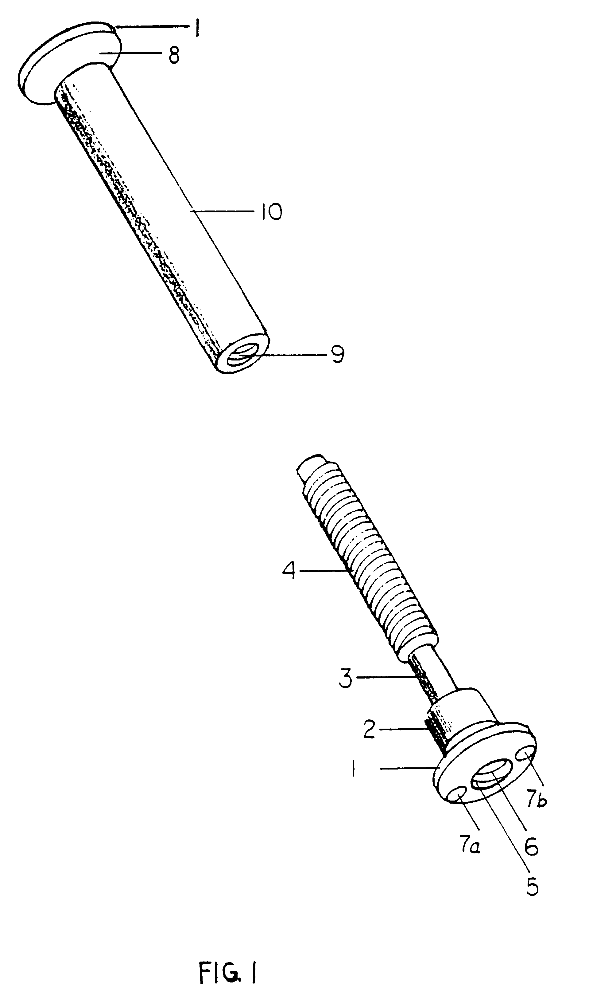
The fastener of this invention, see FIG. 1, consists of a male member with a head 1, shoulder 2, glide shank 3, and threaded portion 4. A hole 6 of sufficient diameter runs clear through both male and female members (they are cannulated) allowing each member to fit over a guide wire. The head is designed to provide for firm attachment to a special insertion tool, FIG. 6. This rigid attachment provides for turning, pulling, pushing and levering of the fastener by the insertion tool. In the preferred embodiment, FIG. 1, the fastener head is internally threaded 5, to receive a threaded male drawtube 11 protruding from the special insertion tool (See FIG. 6). A knob 14 connects to the drawtube 11 providing for rotation thereof. Two pins 13a and 13b protrude from the partial cavity 12 of the installation tool, and these pins mate into two holes 7a and 7b in the head of the fastener. The drawtube pulls the fastener head snugly into the partial cavity (12) wherein it is secured. The shank ...


PUM


Abstract

A high strength fastener for bone fractures. This fastener consists of two members, a male and female. The male member has external machine screw threads that screw into matching internal threads in the female member at a predictable torque so that the force of fixation exerted upon the bone can be approximated by the installer. Because of the effective length of the threads, this fastener is easily adjusted to the proper length without cutting. Both members have a smooth shoulder region proximal to the heads and this shoulder region presents a low-stress bearing surface to each cortical wall. Each member has a head that fits rigidly into an installation tool providing for ease of insertion and fastening in the patient with minimal invasion and little periosteal stripping. Each head has a semi-spherical face that articulates with matching washers and plates, thus allowing the washer to assume the plane of the surrounding bone therefore distributing the load over a greater area.

Description

1. Field of InventionThis invention relates to hardware for the surgical fastening of human and animal bone, especially when it is desirable to affect high strength fastening.2. Discussion of Prior ArtIn the field of Orthopedic surgery, the fastening together of bone fragments using hardware implanted under the soft tissue is known as "internal fixation". The cause of the bone fragmentation may be surgical osteotomy or traumatic fracture. Certain very serious considerations must be addressed when surgically fastening bone. It is necessary to fasten the bone fragments solidly together until the healing process, including osteogenesis, is completed. It is mandatory to affect a suitably tight fastening, so as to prevent excessive motion between the fragments. The repair must not fail; it must be solid enough to resist failure even with loading imposed by minor accidents. The force required to prevent excessive motion is often great. Such great forces may lead to a problem. Fastener for...

Claims


Application Information

Patent Timeline
Patent Type & Authority Patents(United States)
IPC IPC(8): A61B17/80A61B17/68A61B17/88A61B17/86A61B19/00
CPCA61B17/683A61B17/80A61B17/861A61B17/8875A61B17/8877A61B17/8888A61B17/8695A61B2019/301A61B2090/031
Inventor SPRANZA, JOSEPH JOHNHUENE, DONALD R.
Owner ACUMED
Why Eureka
Try Eureka