

Intermediate transfer recording medium, method of forming print, and print
a technology of recording medium and transfer portion, which is applied in the field of intermediate transfer recording medium, method of forming print, and printing, can solve the problems of transfer failure, high cost, and tendency to cause adhesion failure of the transfer portion, and achieve high resolution, high quality, and high quality
- Summary
- Abstract
- Description
- Claims
- Application Information
AI Technical Summary
Benefits of technology
Problems solved by technology
Method used
Image

Examples
example a series
Example A1
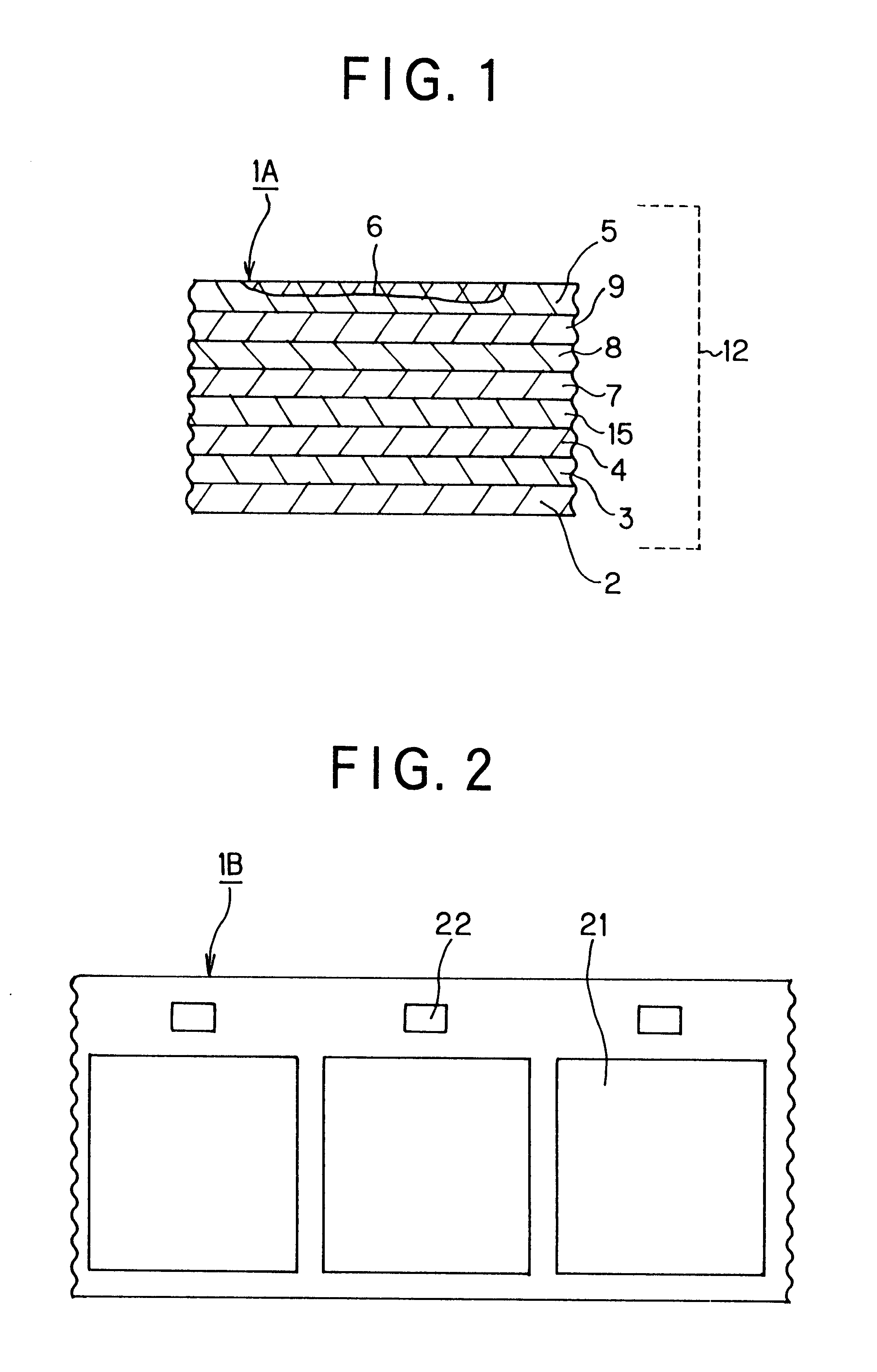
Firstly, a transparent polyethylene terephthalate with a thickness of 12 .mu.m was used as a substrate film 2, the coating solution for peelable layer shown below was applied to the substrate film and dried to form a peelable layer 3 with thickness of 1.5 .mu.m on the substrate film 2.
Acrylic resin: 40 parts by weight
Polyester resin: 2 parts by weight
Methyl ethyl ketone: 50 parts by weight
Toluene: 50 parts by weight
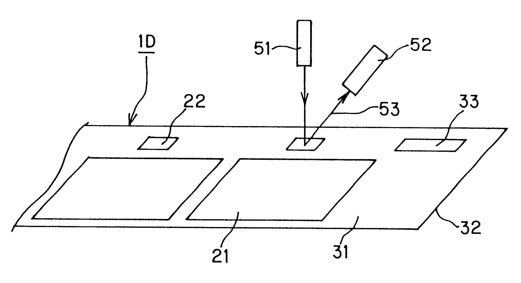
Next, the coating solution for hologram layer shown below was applied to the above peelable layer 3 and dried to form a hologram layer 7 with thickness of 2.0 .mu.m. The formation of a hologram pattern 21 on the hologram layer 7 was performed by forming fine unevenness by embossing processing with the use of an original plate provided with an irregular pattern of interference fringes of a hologram. In addition, a hologram mark 22 was formed by means of the above original plate for embossing process at the same time when the hologram pattern 21 was formed.
Acrylic...
example a2
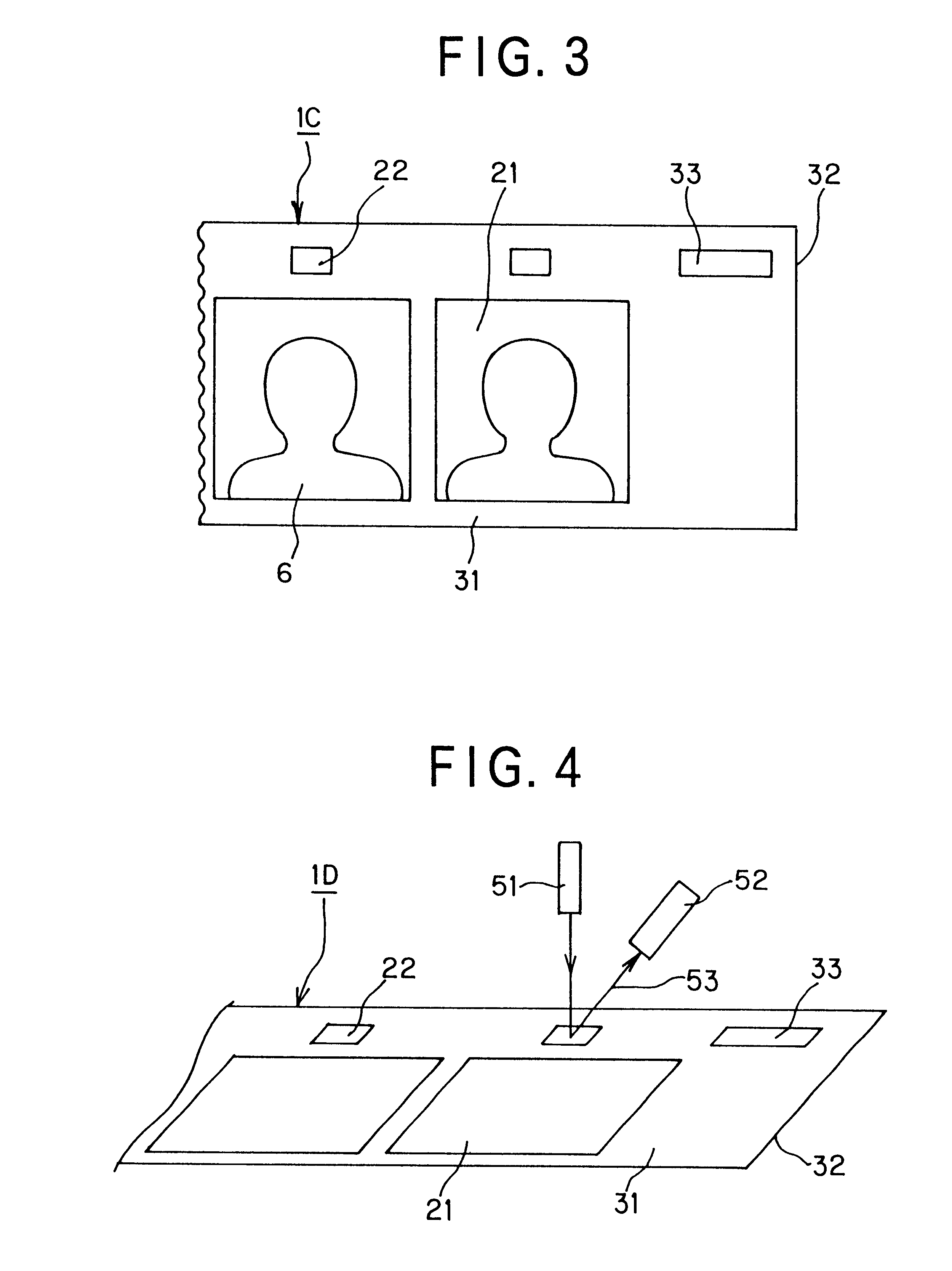
The intermediate transfer recording medium obtained in the above Example A1 was used. Firstly a colored detection mark was transferred to and formed on the receptor layer 5 of the intermediate transfer recording medium by a thermal transfer method using a thermal transfer sheet in which each colorant layer of yellow, magenta and cyan and a colorant layer 78 for colored detection mark was alternately provided side by side. The colorant layer for colored detection mark was a heat-meltable black ink layer. The position where the colored detection mark was formed was set by detecting the hologram mark 22 formed on the hologram layer of the intermediate transfer recording medium in the same manner as in Example A1.
In succession, each colorant of yellow, magenta and cyan was transferred to form an image 6 on the receptor layer 5 of the intermediate transfer recording medium. The position where the image was formed was set by detecting the colored detection mark formed on the receptor laye...
example b series
Example B1
Firstly, a transparent polyethylene terephthalate with a thickness of 12 .mu.m was used as a substrate film 2 and the coating solution for peelable layer shown below was applied to the substrate film and dried to form a peelable layer 3 with thickness of 1.5 .mu.m on the substrate film 2.
Acrylic resin: 100 parts by weight
Polyester resin: 5 parts by weight
Methyl ethyl ketone: 100 parts by weight
Toluene: 100 parts by weight
Next, the coating solution for hologram layer shown below was applied to the above peelable layer 3 and dried to form a hologram layer 7 with thickness of 2.0 .mu.m.
Acrylic resin: 40 parts by weight
Melamine resin: 10 parts by weight
Cyclohexane: 50 parts by weight
Methyl ethyl ketone: 50 parts by weight
Furthermore, a titanium oxide with thickness of 500 angstrom was formed as a transparent deposition layer 8 on the above hologram layer 7 by a vacuum deposition method. The coating solution for receptor layer shown below was further applied to the transparent ...
PUM
| Property | Measurement | Unit |
|---|---|---|
| thickness | aaaaa | aaaaa |
| thickness | aaaaa | aaaaa |
| thickness | aaaaa | aaaaa |
Abstract
Description
Claims
Application Information