Control system for resilient support mechanism such as vehicle suspension mechanism

a technology of resilient support mechanism and control system, which is applied in the direction of shock absorbers, instruments, cycle equipment, etc., can solve the problems of incongruity in control of the suspension mechanism, the control specification (a norm condition) given at the design stage may not be theoretically satisfied, and the design of the control system becomes very complicated

Inactive Publication Date: 2001-11-06
TOYOTA JIDOSHA KK
View PDF8 Cites 137 Cited by
  • Summary
  • Abstract
  • Description
  • Claims
  • Application Information

AI Technical Summary

Problems solved by technology

For this reason, the design of the control system becomes very complicated.
However, as the plant is bilinear, it is obliged to apply an approximate law to a range where a control input would not be realized in the resilient support mechanism such as a suspension mechanism, even if a linear c

Method used


Image

  • Control system for resilient support mechanism such as vehicle suspension mechanism
  • Control system for resilient support mechanism such as vehicle suspension mechanism
  • Control system for resilient support mechanism such as vehicle suspension mechanism

Examples


second embodiment

c.

c1. Design of a Nonlinear H.sub..infin. Output Feedback Control System:

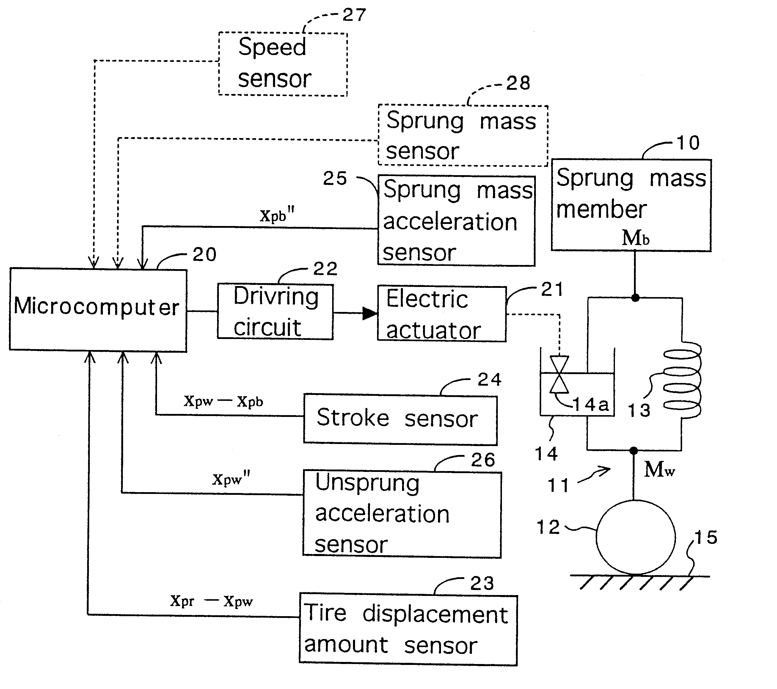
For design of a nonlinear H.sub..infin. output feedback control system, an observer is estimated which includes a portion of the state amount x.sub.p (the tire displacement x.sub.pr -x.sub.pw, relative displacement amount x.sub.pw -x.sub.pb, unsprung mass velocity x.sub.pw ' and sprung mass acceleration x.sub.pb "). In this case, a generalized plant of the output feedback control system is estimated as shown in FIG. 9, wherein the frequency weight is added to the evaluation output z.sub.p and the control input u. In the generalized plant, the evaluation output z.sub.p is multiplied by a nonlinear weight function a.sub.1 (x, x ) after multiplied by the frequency weight W.sub.s (s), while the control input u is multiplied by a nonlinear weight function a.sub.2 (x, x ) after multiplied by the frequency weight W.sub.u (s). Each characteristic of the nonlinear weight functions a.sub.1 (x, x ), a.sub.2 (x, x ) is rep...

third embodiment

d.

d1. Design of a Nonlinear H.sub..infin. Control System of the Kalman Filter Base:

An output feedback system with a Kalman filter used in an observer is designed in a condition where the bilinear factors B.sub.p2 (x.sub.p), D.sub.p2 (x.sub.p) are known. In this embodiment, the same reference characters as those in the second embodiment represent the same factors as those in the second embodiment, and the coefficients aid variables related to a plant are suffixed with "p". The state space of the suspension mechanism is expressed by the following equations (148) and (149).

x.sub.p '=A.sub.p x.sub.p +B.sub.p1 w.sub.1 +B.sub.p2 (x.sub.p)u (148)

y.sub.p =C.sub.p x.sub.p +D.sub.p1 w.sub.2 +D.sub.p2 (x.sub.p)u (149)

In the case that D.sub.p1 is defined as d.sub.p1 =I, the Kalman filter in the case of t.fwdarw..infin. is represented by the following equation.

x.sub.o '=A.sub.p x.sub.o +B.sub.p2 u+K(C.sub.p x.sub.o +D.sub.p2 (x.sub.p)u-y) (150)

Provided that, x.sub.o, x.sub.o ' each are an estima...


PUM


Abstract

A control system for a resilient support mechanism such as a suspension mechanism of a wheeled vehicle including a damper disposed between an unsprung mass member and a sprung mass member of the vehicle, wherein a damping coefficient of the damper is divided into a linear portion and a nonlinear portion, and wherein the nonlinear portion of the damping coefficient is defined as a control input u and applied with a frequency weight Wu(s), while a vertical velocity of the sprung mass member, a relative velocity of the sprung mass member to the unsprung mass member and a vertical acceleration of the sprung mass member are defined as an evaluation output zp and applied with a frequency weight Ws(s). In the control system, a nonlinear Hinfin control theory is applied to a generalized plant to obtain a positive definite symmetric solution P and to calculate a target damping force based on the positive definite symmetric solution P and a state amount such as the vertical velocity of the sprung mass member, a relative displacement of the sprung mass member to the unsprung mass member or the like.

Description

1. Field of the InventionThe present invention relates to a resilient support mechanism for resiliently supporting the component structure of a wheeled vehicle. More particularly, the present invention is concerned with a control system for a resilient support mechanism such as a suspension mechanism disposed between an unsprung mass and a sprung mass of the wheeled vehicle for controlling a damping force or a damping coefficient of a shock absorber or damper device assembled therein.2. Discussion of the Prior ArtIn a conventional suspension mechanism of a wheeled vehicle, an amount of movement state of a sprung mass or an unsprung mass of the vehicle is detected to determine a target damping force or a target damping coefficient on a basis of the detected amount of movement state thereby to adjust the damping force or damping coefficient of a shock absorber or damper device assembled in the suspension mechanism to the target damping force or damping coefficient. Disclosed in Japane...

Claims


Application Information

Patent Timeline
IPC IPC(8): B60G17/015B60G17/018F16F15/02G05B13/02G05B13/04
CPCB60G17/018B60G2600/184
Inventor OHSAKU, SATORUKAMIMURA, ICHISEI
Owner TOYOTA JIDOSHA KK
Why Eureka
Try Eureka