Production process of varying thickness osteosynthesis plates

a technology of osteosynthesis and production process, which is applied in the direction of layered products, paper/cardboard articles, lamination, etc., can solve the problems of difficult plate manufacturing, inability to meet biocompatible materials, and difficult plate adjustment to the bone surface by bending, etc., to achieve easy and economical way, high thermal conductivity, and better fitting to the bone surface

Inactive Publication Date: 2001-11-13
MAGRINI ANNA
View PDF6 Cites 63 Cited by
  • Summary
  • Abstract
  • Description
  • Claims
  • Application Information

AI Technical Summary

Benefits of technology

The invented process is based on the fact that the composite structure manufactured in the said way, gives to the layer of the material which will become the osteosynthesis plate, a structural strength able to resist to the stress produced by the metal cutting. The size of the composite structure can be set in such a way to permit the mechanical clamping of the composite structure to the machine tool by using commercially available fixing devices. The heat generated by the metal cutting is dissipated by the bearing layer thank to its high thermal conductivity, avoiding in this way the heating of the adhesive layer above temperature at which the softening of the adhesive begins. The final separation of the plate from the bearing layer is carried out by exploiting the softening of the adhesive layer which usually for structural adhesives appears at temperature over 80.degree. C. Otherwise it is possible to melt the adhesive layer by adopting a th

Problems solved by technology

In these areas the adjustment of the plate to the bone surface done by bending can therefore be more difficult than needed.
In general the complex shape, the small size, the limited thickness in the proximal and distal areas of the plate make difficult the manufacturing of plates by metal cutting processes which would be necessary to obtain varying thickness, unless a system for fixing adequately the machined plate is available.
Fixing systems of magnetic type do not work with biocompatible materials such as titanium and stainless steel generally used for osteosynthesis plates.
Other clamping systems of mechanical type in which the fastening is carried out by pressure on the workpiece do not permit to machine the plate without interruptions for changing the clamping zone and completing the operation in the plate areas p

Method used


Image

  • Production process of varying thickness osteosynthesis plates
  • Production process of varying thickness osteosynthesis plates

Examples


Embodiment Construction

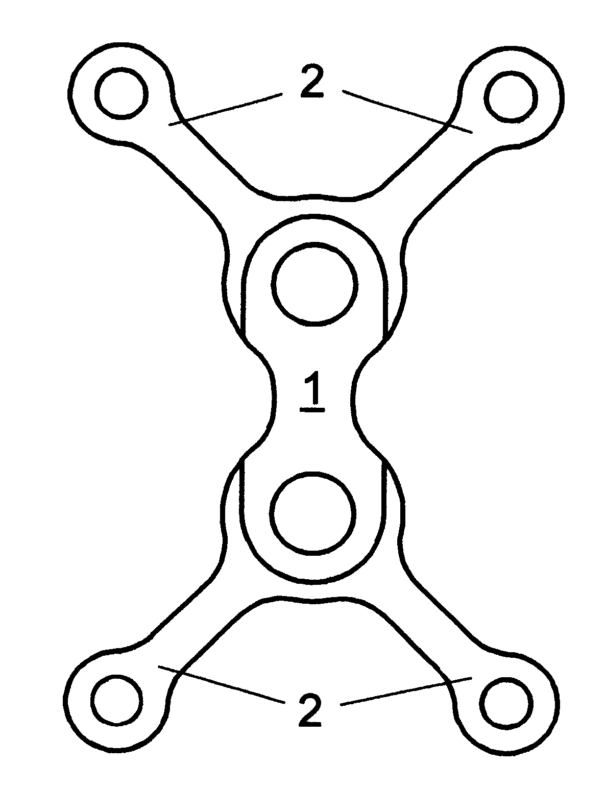
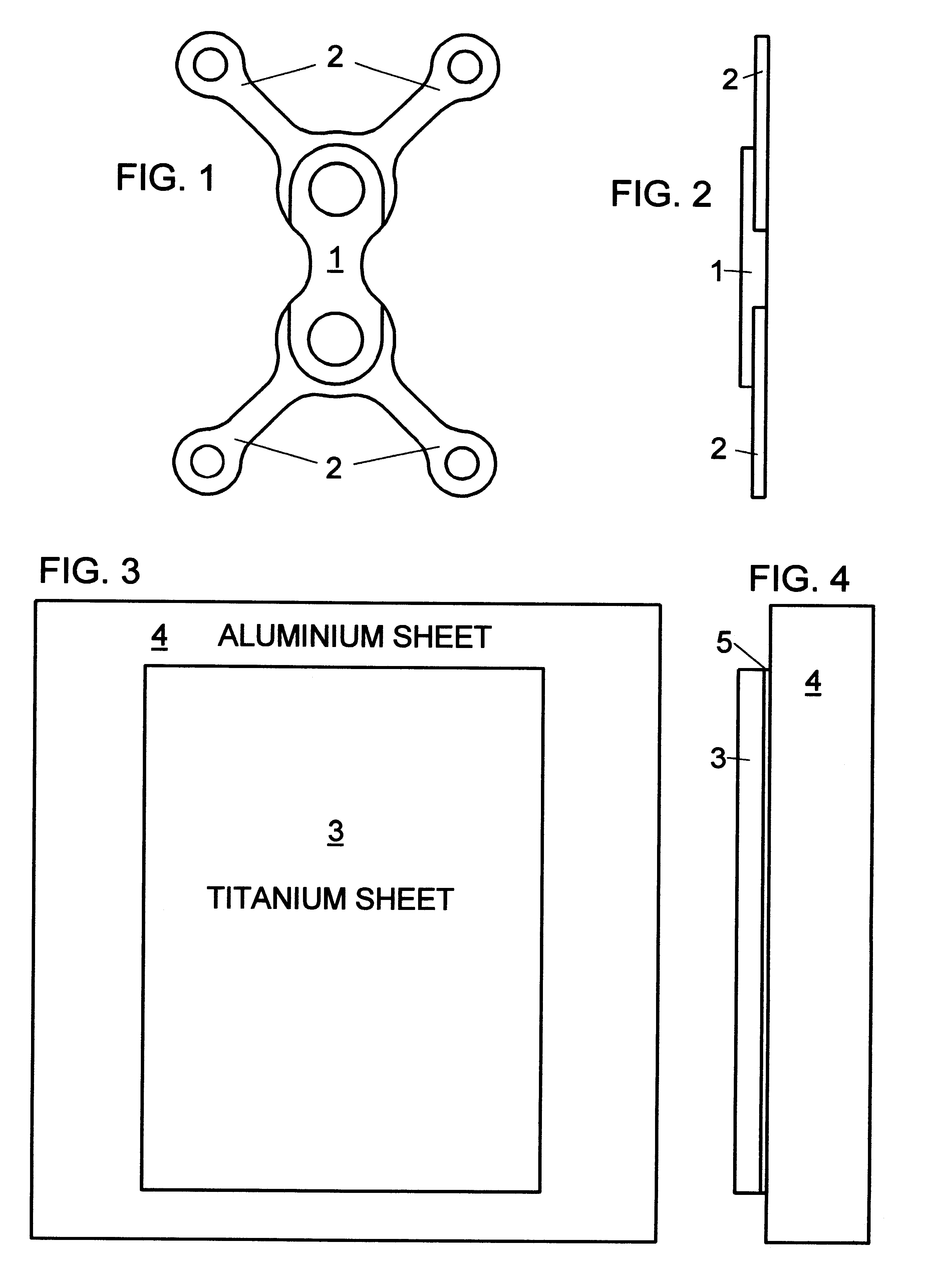
The best mode of carrying out the invented process is described considering the manufacturing of the osteosynthesis plate with reference to the accompanying drawings. The plate material is commercially pure titanium. The shape of the plate, indicated in FIG. 1, is an example of an osteosynthesis plate with a double Y configuration characterised by different thickness in the proximal area 1 and in the distal areas 2. Thickness in the proximal area is 1.00 mm, thickness in the distal areas is 0.50 mm. The production process requires to manufacture the composite structure (FIGS. 3, 4) consisting of a commercially pure titanium sheet (3) with a thickness of 1.05 mm, bound by a cyanoacrylate layer (5) to an aluminium sheet (4). The aluminium sheet is larger than the titanium plate, and its thickness is 4 mm. The composite structure is clamped to the worktable of a milling machine which performs the drilling operations, the surfaces generation according to the required thickness, the cont...


PUM

PropertyMeasurementUnit
Angleaaaaaaaaaa
Temperatureaaaaaaaaaa
Thicknessaaaaaaaaaa

Abstract

The invention concerns a process for the production of osteosynthesis plates with a varying thickness to whatever degree. The plates are manufactured by a metal cutting process carried out on a composite structure made by a layer of the material which will form the osteosynthesis plate, bound through a layer of adhesive to a supporting layer with high thermal conductivity and mechanical strength. When the cutting process terminates, the osteosynthesis plate is separated from the supporting layer by heating the composite structure until the adhesive melts or by using a thinner suitable for the adopted adhesive.

Description

The invention relates to a process for the production of plates for osteosynthesis with a varying thickness thin to whatever degree.Plates which are presently used to achieve osteosynthesis have a constant thickness due to the adopted production process. Said process consists in cutting, usually by laser, the plate from a sheet of biocompatible metal characterised by a constant thickness, following the plate contour, and in making the countersink holes for the screws heads by plastic deformation of the metal around the holes.Osteosynthesis plates with constant thickness should have a thickness dimensioned in order to bear the tension in the most stressed section near the fracture or osteotomy line (proximal area). This thickness is however greater than the thickness required by the stress present in the sections farther from proximal area (distal areas). In these areas the adjustment of the plate to the bone surface done by bending can therefore be more difficult than needed. Anothe...

Claims


Application Information

Patent Timeline
IPC IPC(8): A61B17/80A61B17/68
CPCA61B17/80Y10S83/953Y10T156/1082Y10T156/108Y10T156/1052Y10T83/0486Y10T83/0405Y10T83/04
Inventor MAGRINI, ANNACARTA, MAURIZIO
Owner MAGRINI ANNA
Why Eureka
Try Eureka