Electrically operated viscous fluid dispensing apparatus and method

a technology of electric operation and viscous fluid, which is applied in the direction of lighting and heating apparatus, process and machine control, instruments, etc., can solve the problems of short short service life of electric fluid dispensers, and rapid increase of coil temperature, so as to improve the service life and improve the viscosity of fluid within the dispenser. , the effect of reducing the range of temperature fluctuations

Inactive Publication Date: 2001-11-20
NORDSON CORP
View PDF9 Cites 51 Cited by
  • Summary
  • Abstract
  • Description
  • Claims
  • Application Information

AI Technical Summary

Benefits of technology

The present invention provides an improved electric dispenser for viscous fluids that manages the thermal condition of the dispenser directly to provide a substantially improved, more consistent dispensing of viscous fluids. The electric dispenser of the present invention provides more consistent actuation of the dispensing valve independent of changes in the speed of operation of the dispenser. The electric fluid dispenser of the present invention reduces the range of temperature fluctuations resulting from changes in speed of the production line and changes in the frequency of operation of the fluid dispenser. Further, the electric fluid dispense

Problems solved by technology

However, pneumatic dispensers have disadvantages in that they generally have a shorter life than electric fluid dispensers, and the operation of the pneumatic solenoid is subject to less precise control than the electric solenoid in an electric fluid dispenser.
In the operation of an electric viscous fluid dispensing gun, the coupling between the coil and the armature is not efficient; and therefore, in order to achieve the highest actuation speed, a current pulse or spike is typically provided to the coil during an initial turn-on period in order to initiate the motion of the armature as quickly as possible.
However, maintaining such a level of current to the coil quickly and substantially increases coil temperature.
Further, maintaining such a high level of current increases the time required for the energy stored in the coil's inductance to dissipate, thereby increasing the turn-off time and the time required to close the fluid dispenser.
However, as is described below, the operation of the coil and armature during the fluid dispensing process creates other heat related issues that impact the quality of the fluid dispensing process.
For example, the electric coil of an electric dispensing valve normally is not capable of

Method used


Image

  • Electrically operated viscous fluid dispensing apparatus and method
  • Electrically operated viscous fluid dispensing apparatus and method
  • Electrically operated viscous fluid dispensing apparatus and method

Examples


Embodiment Construction

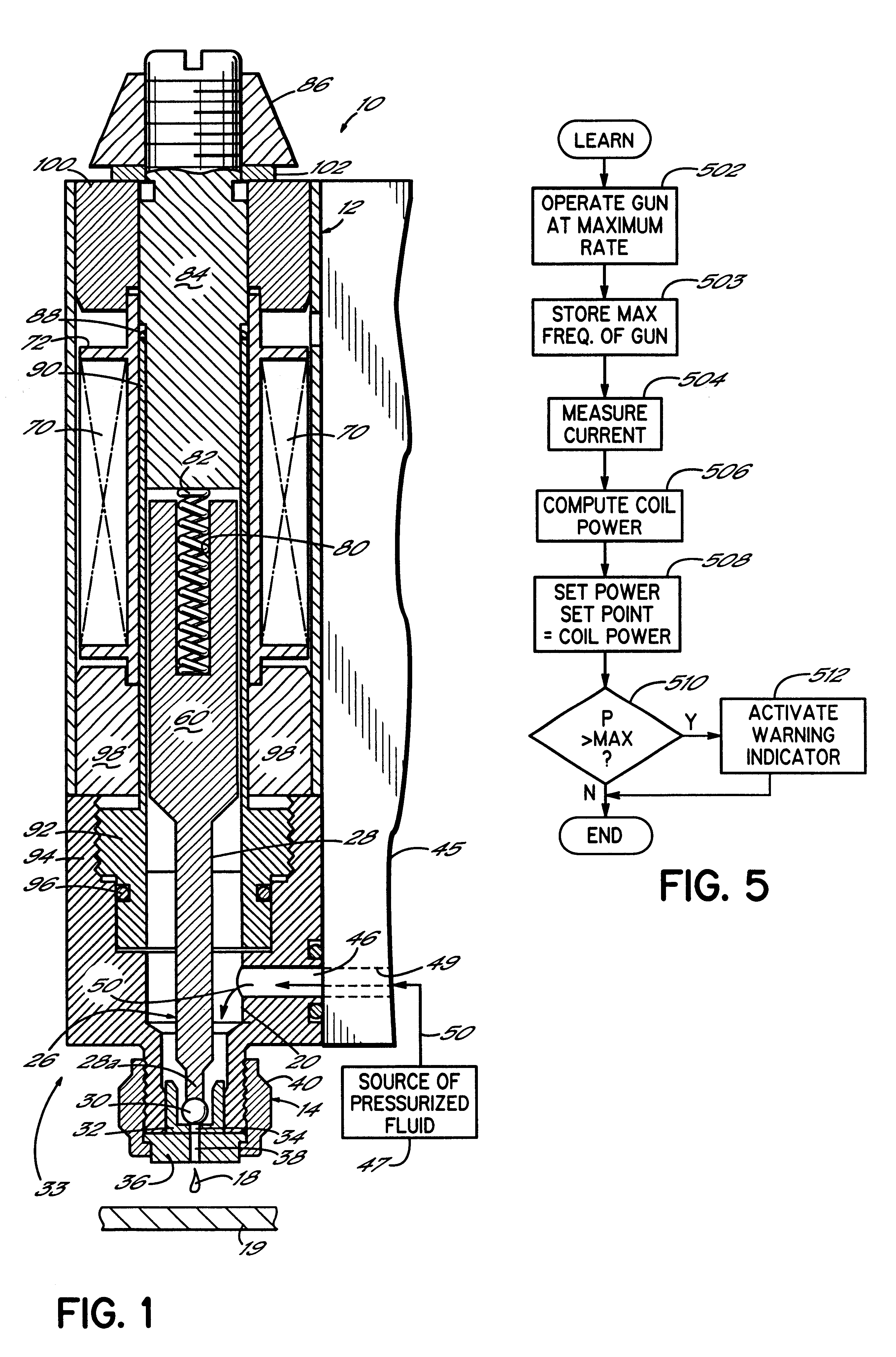
Referring first to FIG. 1, an electrically operated viscous fluid dispenser or dispensing gun 10 comprises one or more dispensing modules or valves 33 mounted on a fluid distribution manifold plate 45 in a known manner. The dispensing valve 33 includes a dispenser body 12 and a fluid dispensing nozzle body 14. The dispenser 10 is adapted for dispensing high viscosity fluids, such as a hot melt adhesive, but other dispensed fluids can benefit from the invention as well. Such other fluids include soldering fluxes, thermal greases, heat transfer compounds and solder pastes. Furthermore, the dispenser 10 is mounted in a dispensing machine or system (not shown) in a known manner to dispense fluids in discrete amounts, preferably as droplets or dots, but alternatively in continuous beads. As shown in FIG. 1, the dispenser body 12 used in conjunction with the fluid dispensing nozzle body 14 is particularly constructed to dispense droplets 18 of the viscous fluid onto a substrate 19. Relati...


PUM


Abstract

An electrically operated fluid dispenser for dispensing a pattern of viscous fluid onto a substrate during a run mode. The dispenser is turned off and does not dispense the viscous fluid during a standby mode of operation. The dispenser includes a dispenser body having an outlet and an armature disposed in the dispenser body for movement between an opened position allowing a fluid flow from the outlet and a closed position preventing the fluid flow from the outlet. A coil is mounted adjacent the armature and selectively generates an electromagnetic field for moving the armature between the opened and closed positions. A controller includes different apparatus and methods for using the coil as a heater as well as providing other heat transfer devices on the dispensing valve to maintain a constant temperature either, during only the run mode or, during both, the run and the standby modes. The above dispensing valve heating control facilitates a design of an electrically operated fluid dispenser having a body with a fluid passage intersecting first and second sides of the body and a dispensing outlet in fluid communication with the fluid passage. The dispenser includes a heater and has feed member mounted to the first side of the body with one end of the fluid passage in the feed plate fluidly connecting with one end of the fluid passage in the dispenser body. The dispenser also has an cap mounted to the second side of the dispenser body to terminate the fluid passage on the second side of the dispenser body.

Description

FIELD OF THE INVENTIONThe present invention generally relates to an apparatus for dispensing viscous fluids and more specifically, to an electrically operated apparatus for dispensing viscous liquids, such as hot melt adhesives.BACKGROUND OF THE INVENTIONPneumatic and electric viscous fluid dispensers have been developed for dispensing applications requiring precise placement of a viscous fluid. Pneumatic dispensers have a significant advantage in that the pneumatic solenoid operating the dispensing valve can be made very strong, so that the dispensing valve operation is essentially independent of the viscosity of the fluid being dispensed. However, pneumatic dispensers have disadvantages in that they generally have a shorter life than electric fluid dispensers, and the operation of the pneumatic solenoid is subject to less precise control than the electric solenoid in an electric fluid dispenser. Therefore, in some applications, electrically operated viscous fluid dispensers are pr...

Claims


Application Information

Patent Timeline
IPC IPC(8): B05C5/02B05C5/00B05D1/26B05C5/04B05C9/14B05C11/10B05D3/00B05D3/14
CPCB05C5/001G05D23/1919B05C5/0279B05C5/0237
Inventor ESTELLE, PETER W.SAIDMAN, LAURENCE B.SCHMIDT, PAUL
Owner NORDSON CORP
Why Eureka
Try Eureka