

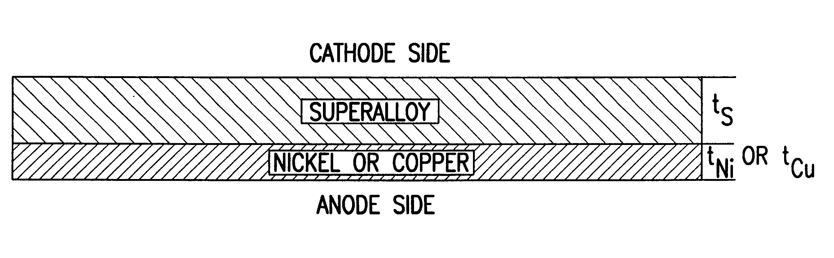
Solid oxide fuel cell interconnector
a fuel cell and interconnector technology, applied in the direction of cell components, electrochemical generators, cell component details, etc., can solve the problem of adversely affecting the kinetics of oxide growth
- Summary
- Abstract
- Description
- Claims
- Application Information
AI Technical Summary
Benefits of technology
Problems solved by technology
Method used
Image

Examples
example
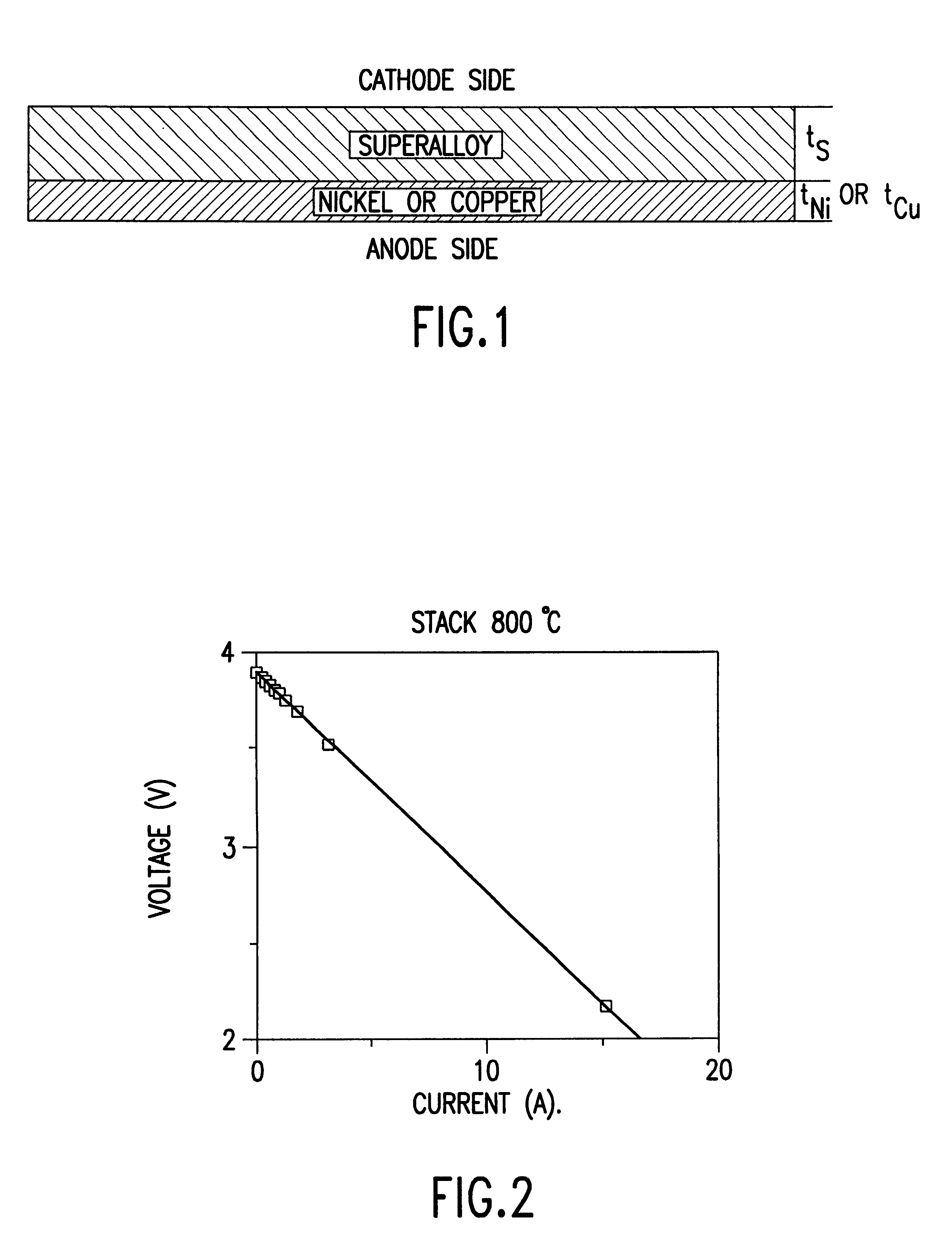
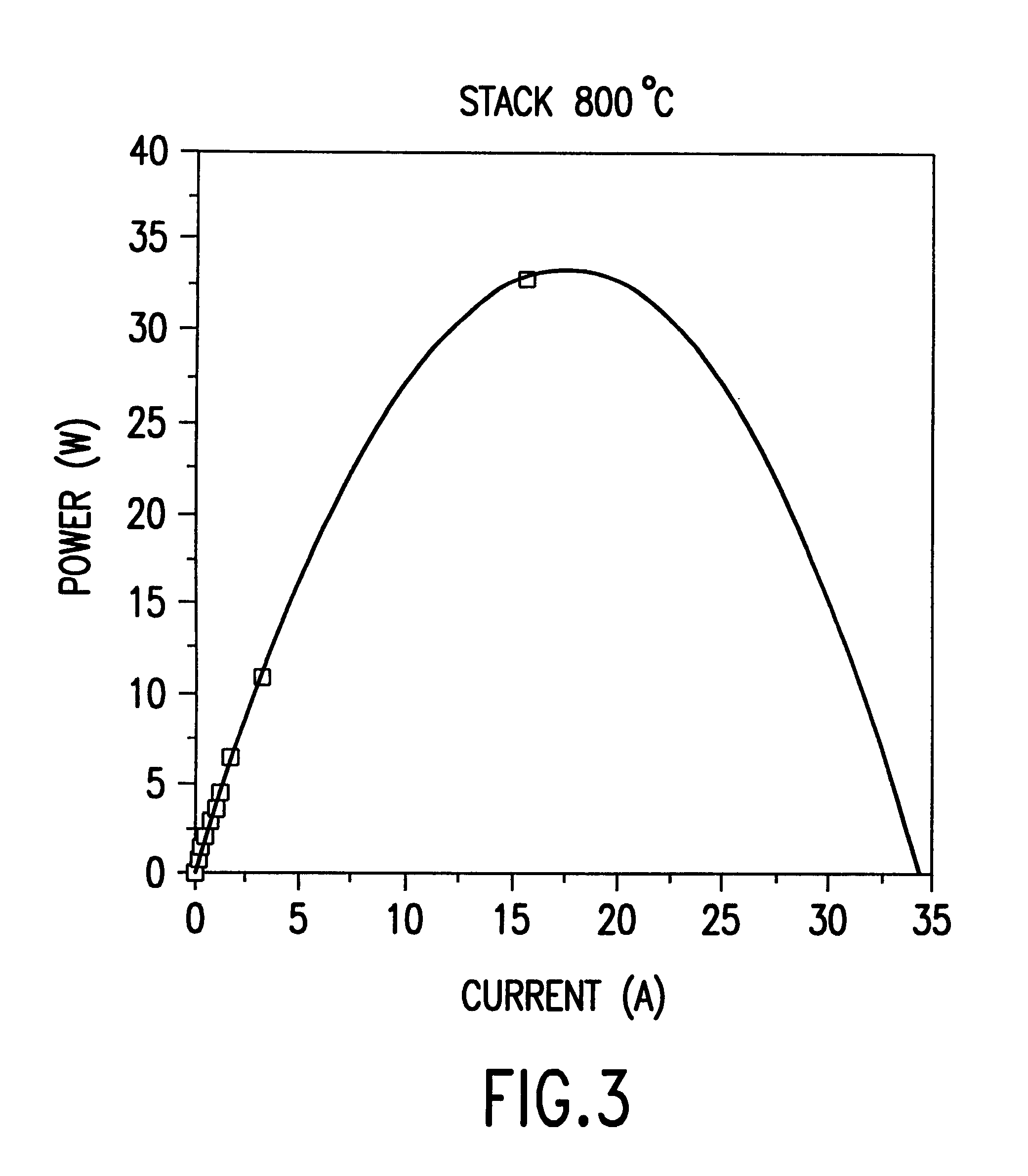
Stack testing was conducted with copper-plated Haynes 230 interconnectors in accordance with this invention. The initial step was the fabrication of corrugated anode-supported cells. NiO and 8 mol. % yttria stabilized zirconia (YSZ) powders were mixed and ball-milled in ethanol for 24 hours. After the well-mixed slurry was dried under vacuum, the powder was die-pressed using corrugated dies such that the flow pattern was in a cross-flow arrangement. The amount of powder per plate was 45 g, and pressed dimensions were about 7 cm.times.7 cm in lateral dimensions and 4 mm in thickness after uniaxial pressing. The corrugated plates were bisqued in air at 1000.degree. C. for 1 hour. A slurry of YSZ in either ethylene glycol or ethanol was made with a ratio of 2 g YSZ per 10 ml ethylene glycol. The NiO+YSZ corrugated plates were subsequently painted (or spray-coated) with the YSZ slurry. The corrugated plates were then sintered in air at 1400.degree. C. for two hours.
La.sub.0.8 Sr.sub.0.2...
PUM
| Property | Measurement | Unit |
|---|---|---|
| thickness | aaaaa | aaaaa |
| temperatures | aaaaa | aaaaa |
| temperatures | aaaaa | aaaaa |
Abstract
Description
Claims
Application Information