Casing for a steam or gas turbine

a gas turbine and compression casing technology, applied in the direction of motors, liquid fuel engines, non-positive displacement pumps, etc., can solve the problems of reduced efficiency, severe deformation of the shell, and the change of the round shape of the casing, so as to reduce the radial clearance, avoid expensive designs and assembly jigs, and prevent the effect of poor efficiency

a gas turbine and compression casing technology, applied in the direction of motors, liquid fuel engines, non-positive displacement pumps, etc., can solve the problems of reduced efficiency, severe deformation of the shell, and the change of the round shape of the casing, so as to reduce the radial clearance, avoid expensive designs and assembly jigs, and prevent the effect of poor efficiency

US6336789B1Inactive Publication Date: 2002-01-08GENERAL ELECTRIC TECH GMBH

Image

  • Casing for a steam or gas turbine
  • Casing for a steam or gas turbine

Examples


Embodiment Construction

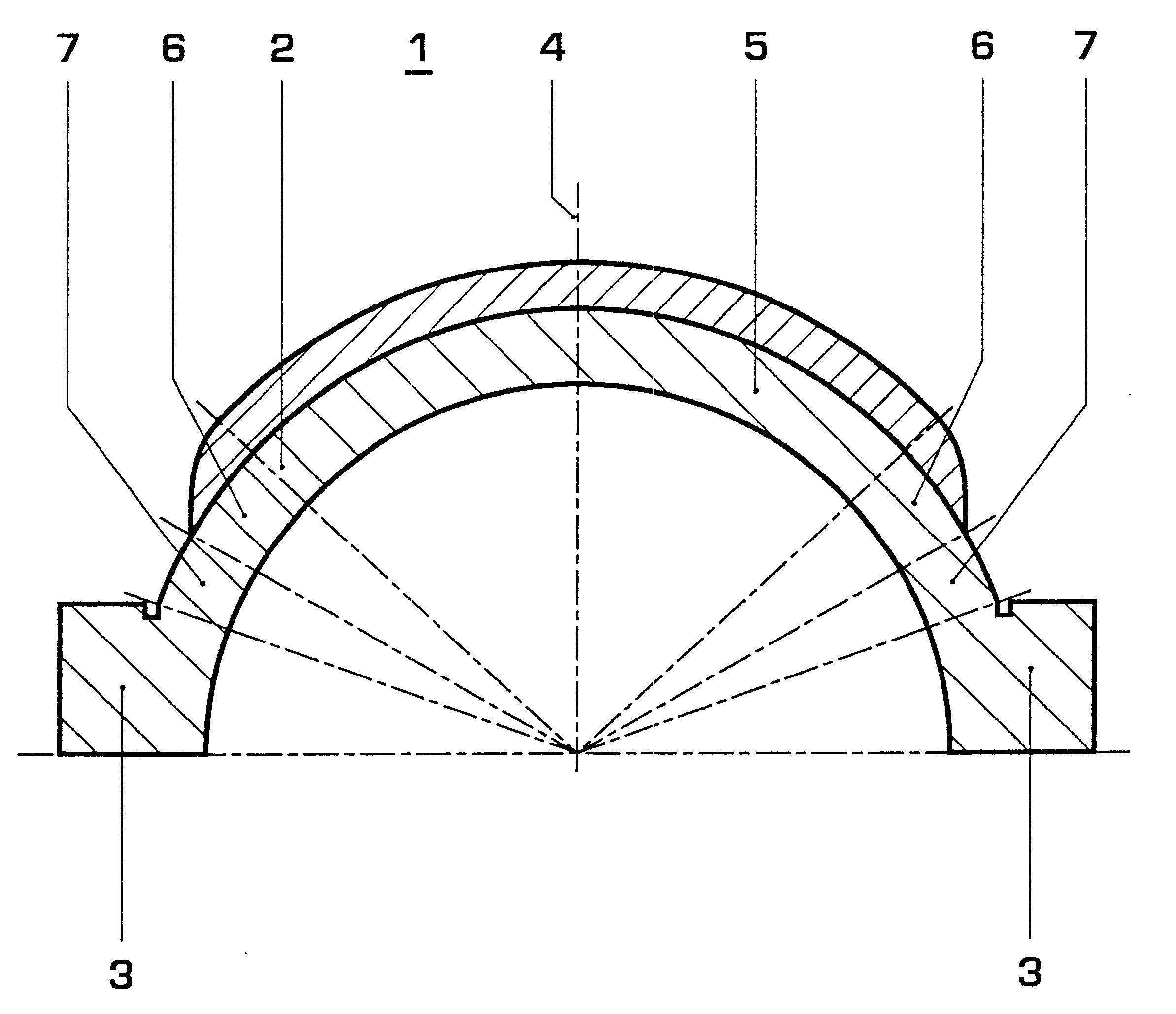
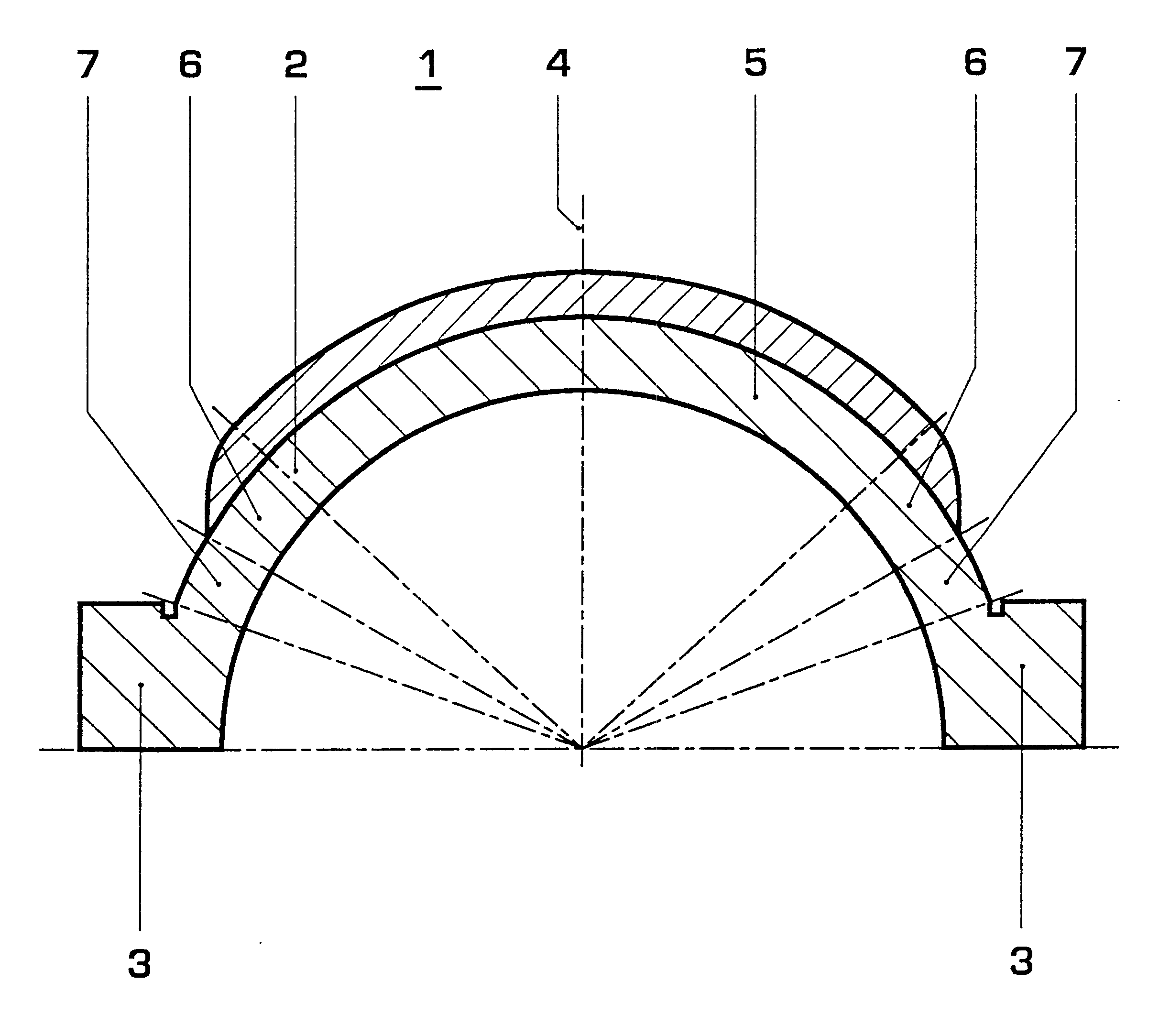
The object of the invention is to design a casing for a steam or gas turbine, which retains its round shape in operation or exhibits only relatively minor deformation, in order in this way to reduce the radial clearance between the casing and the ends of the turbine blades and to prevent the poorer efficiency associated with this. Furthermore, it is intended to avoid expensive designs and assembly jigs.

This object is achieved according to the invention in that the shell has different wall thicknesses in the upper region facing away from the flanges, in two central regions and in two lower regions facing the flanges, in which case the wall thickness of the upper region facing away from the flanges is reinforced in comparison with the wall thickness of the lower regions facing the flanges, and the wall thickness of the central regions is variable such that the upper region facing away from the flanges and the lower regions facing the flanges merge continuously into one another.

One adv...


PUM


Abstract

A casing for a steam or gas turbine comprises a shell and two flanges. The wall thickness of the shell is varied in an upper region facing away from the flange, in two central regions and in two lower regions facing the flanges, such that the upper region facing away from the flanges is reinforced in comparison with the lower regions facing the flanges. The lower regions facing the flanges are more flexible than the flanges which are attached by screws, and the partially reinforced central region and the reinforced upper region, and act as a joint to compensate for deformation, particularly in the radial direction. Consequently, the casing remains considerably more round in operation. The reduced radial clearance (achieved by reduced deformation) between the casing and the ends of the turbine blades leads to considerably increased efficiency during operation of the turbine.

Description

The invention relates to a casing for a steam or gas turbine, which comprises a shell and two flanges.PRIOR ARTCompressor casings for gas turbines are known, which comprise a shell and two flanges. These casing have a pseudo-flange in the upper and lower region of the shell. These, however, have the disadvantage that increased radial expansion occurs in the region of the pseudo-flange during operating of the gas turbine owing to the higher mean temperature, and the casing thus changes from its round shape. This deformation leads to reduced efficiency, since the gap between the casing and the ends of the turbine blades is enlarged, and steam or air can flow through without any impediment at this point, without carrying out any work on the turbine.Casings for steam turbines are also known, which comprise a shell and two flanges and which have vertical slits in the horizontal flanges. However, owing to the temperature distribution in the shell and the flanges, this leads to the shell b...

Claims


Application Information

Patent Timeline
08 Jan 2002
Publication
US6336789B1
IPC
F01D25/24; F01D25/26
CPC
F01D25/26; F01D25/24
Inventors
BEERENS, CHRISTOPH; HUSTER, JOSEF