Flexible wedge gate valve

Inactive Publication Date: 2002-01-15
KALSI ENG
View PDF3 Cites 39 Cited by
  • Summary
  • Abstract
  • Description
  • Claims
  • Application Information

AI Technical Summary

Problems solved by technology

Under high fluid load the metal of the guide ear elements can be subjected to plastic deformation at the uppermost and lowermost portions thereof, resulting in galling of the guide surfaces and unpredictably large thrust to operate the valve.
If the guide ear elements of FIG. 2 were longer so that the lower ends of the guide ear elements were positioned lower than the horizontal fluid load so that tilting due to overhung load was eliminated, high peak contact stresses would still be concentrated at the lower end of the guide ear elements throughout much of the stroke, causing plastic deformation, galling, and unpredictably large thrust requirements.
In severe cases, gross material loss at the lower ends of the guide ear elements can cause disk tilting even when the guide ear elements are relatively long.
With the disk in the intermediate travel position, the high flow velocities and high differential pressure across the disk cause high internal reactions at the sliding interfaces of the valve internal components.
Under high differential pressure conditions, the localized stresses at these two points become extremely high, causing severe plastic deformation, gouging, and machining damage to both the disk and the seat faces.
The damage not only degrades the shut-off capability of the valve, it al

Method used


Image

  • Flexible wedge gate valve
  • Flexible wedge gate valve
  • Flexible wedge gate valve

Examples


Embodiment Construction

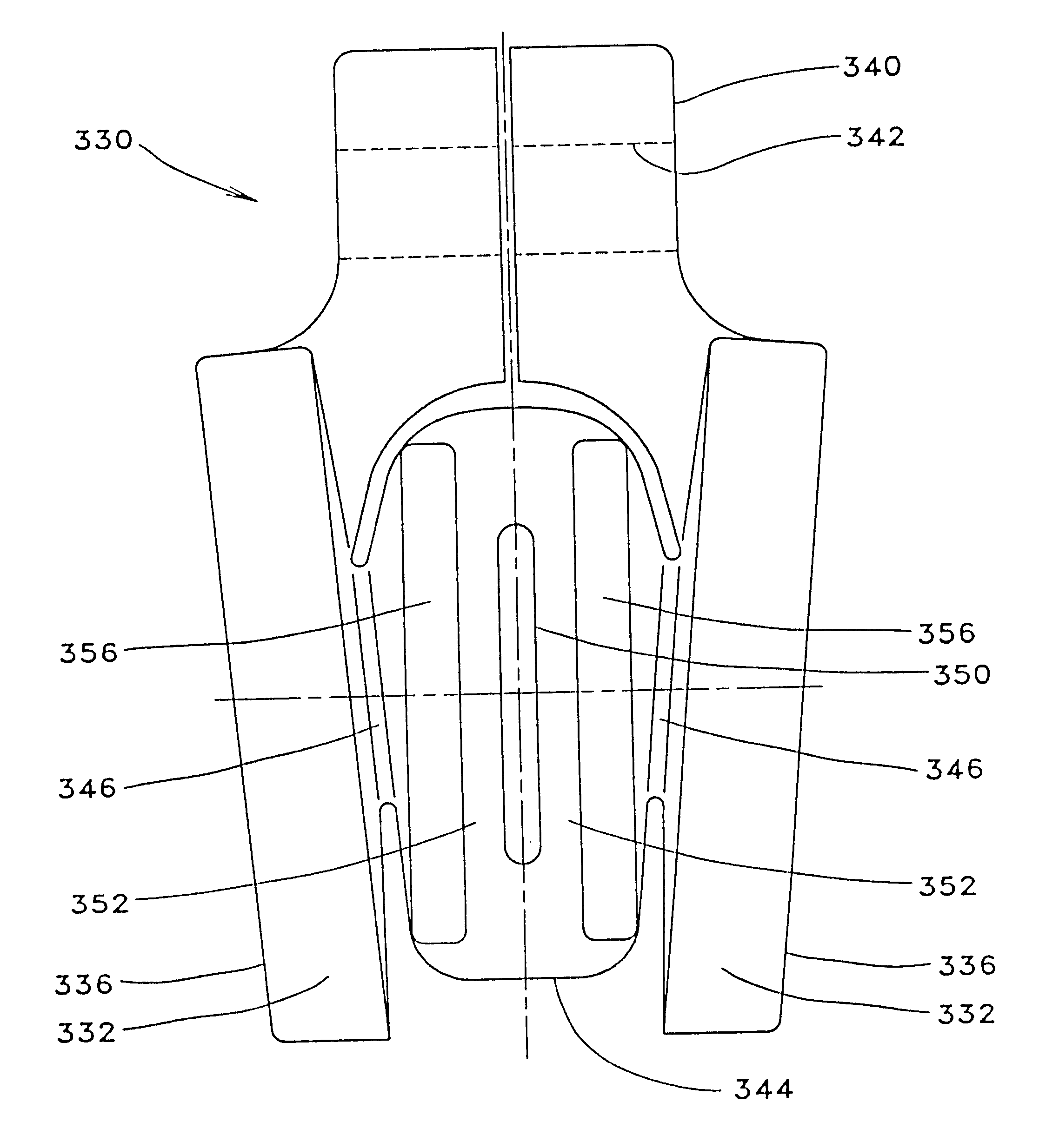
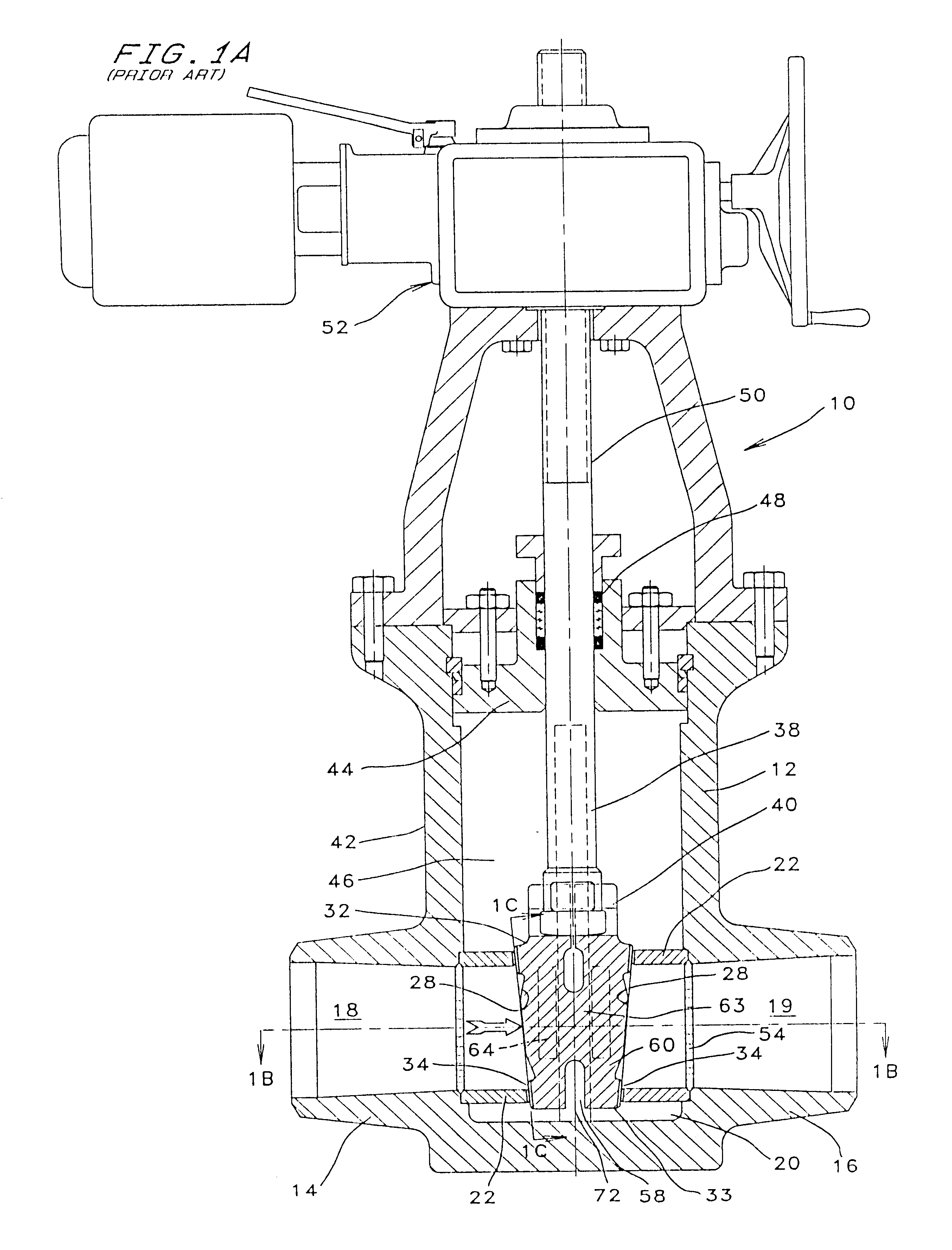
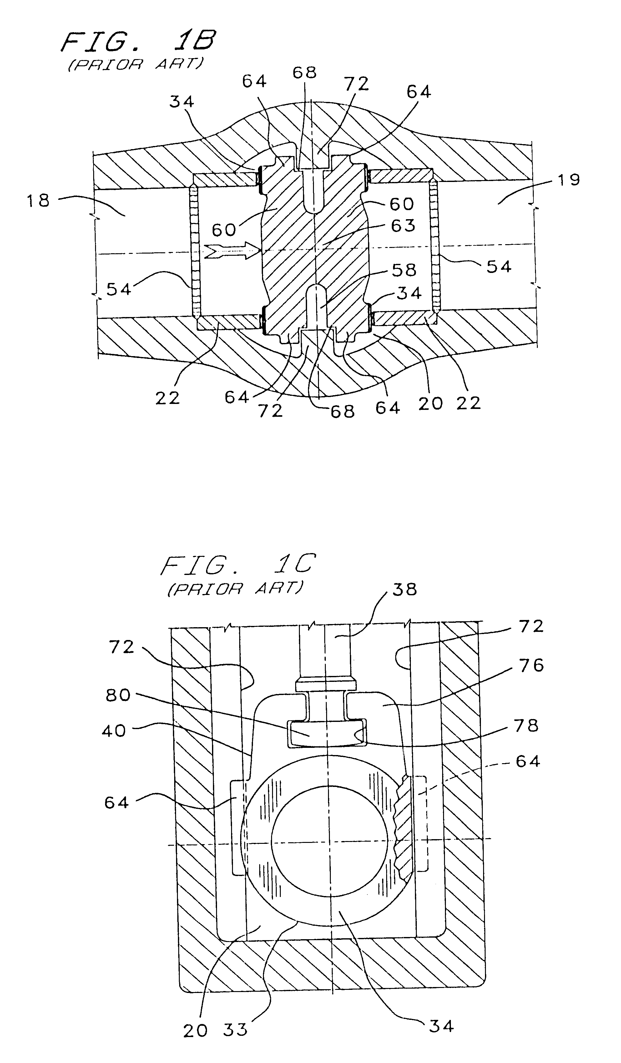
The preferred embodiment of the improved valve assembly of the present invention combines a disk as shown in FIGS. 9A, 9B & 9C and the stem downstop member described above in conjunction with FIG. 8 which are adapted to be installed within the conventional valve / actuator arrangement typified by FIG. 1A. FIG. 9A is a front view of the preferred disk embodiment, FIG. 9B is a side view, and FIG. 9C is a sectional view taken along line 9C--9C of FIG. 9A.

The preferred embodiment of the improved disk of this invention, being shown generally at 160 is of single-piece, integral construction (forged or cast) which consists of two pressure boundary plates 162 that are integrally connected to the center section 166 of the disk by smaller diameter hub sections 168. As shown in FIG. 9B, the sealing faces 163 of the two pressure boundary plates are oriented in downwardly converging relation and define a wedge shape similar to that in the conventional wedge gate valve design. The preferred wedge a...


PUM


Abstract

A wedge gate valve having a valve body defining a valve chamber and flow passages and upwardly diverging circular seat surfaces of circular, flat configuration and defining seat planes. A valve disk or wedge having downwardly converging sealing surfaces is movable within said valve chamber between open and closed positions for controlling flow through the valve. Pressure boundary plates connected by hubs to the valve disk define the sealing surfaces of the disk and have bottom corners that establish line contact with the downstream seat surface and prevent any portion of said sealing surfaces of said valve disk from crossing the sealing plane of the downstream seat in the event of flow responsive downstream movement of the valve disk during its opening and closing movement. Guide ears of the disk are provided with flexible upper and lower extremities and rounded or chamfered inner end surfaces to minimize localized peak contact stress with disk guide rails of the valve body. The center section of the disk is rendered flexible by the provision of an internal transverse cavity that extends completely through the center section or is located centrally of the center section to define flexible walls between the hubs to thus provide for disk flexibility for overcoming the tendency for disk binding. A valve actuator for opening and closing the valve disk is provided with an adjustable downstop to prevent overtravel of the disk during seating.

Description

This invention relates generally to wedge gate valves in fluid flow systems and more specifically concerns flexible wedge gate valves having features to prevent pinching, thermal binding, and overloading due to over-travel, and to prevent damage to valve seats and disks which typically occurs when a wedge gate valve is opened or closed under conditions of high pressure and high fluid flow.The flexible wedge gate valve shown in FIG. 1A (prior art) is the most commonly used isolation valve in critical service applications in nuclear and fossil fuel electric power generation plants and in petrochemical plants where reliable sealing under high temperature is an important requirement. In safety-related systems, these valves are operated by an electric motor actuator, and the valve and actuator assembly is commonly referred to as "motor-operated valve" (MOV).The closing function of the MOV is achieved by moving the wedge into a seated position that blocks the fluid flow. Motion imparted t...

Claims


Application Information

Patent Timeline
IPC IPC(8): F16K3/12F16K3/02
CPCF16K3/12
Inventor KALSI, MANMOHAN SINGHALVAREZ, PATRICIO DANIELWANG, JAW-KUANG
Owner KALSI ENG
Why Eureka
Try Eureka