Apparatus for and method of controlling internal combustion engine

a technology of internal combustion engine and apparatus, which is applied in the direction of electrical control, non-mechanical valves, gearing, etc., can solve the problems of fuel consumption under partial load worsening

Inactive Publication Date: 2002-02-05
HITACHI LTD
View PDF26 Cites 40 Cited by
  • Summary
  • Abstract
  • Description
  • Claims
  • Application Information

AI Technical Summary

Problems solved by technology

On the other hand, a conventional gasoline engine has a drawback that although the maximum output or power is high because of a premixture combustion, the fuel consumption under a partial load is worsened because of a pumping loss.

Method used


Image

  • Apparatus for and method of controlling internal combustion engine
  • Apparatus for and method of controlling internal combustion engine
  • Apparatus for and method of controlling internal combustion engine

Examples


first embodiment

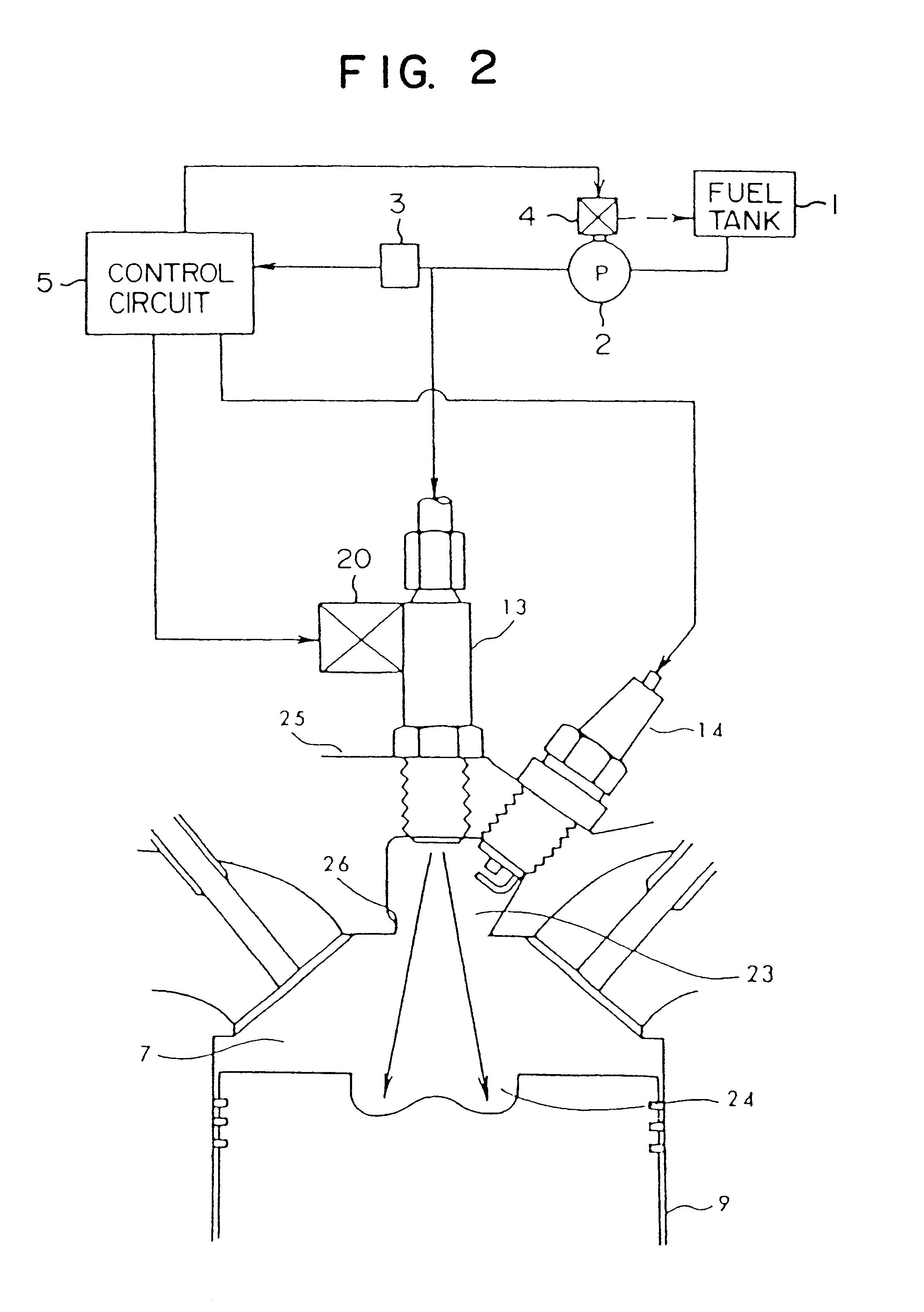
the present invention will now be described with reference to FIG. 2 which is a vertical cross-sectional view of the combustion chamber. The fuel injection valve 13 and the ignition plug 14 are provided at an auxiliary combustion chamber 23 formed at an engine head 25. With respect to the positional relation between the fuel injection valve 13 and the ignition plug 14, it is preferred that the ignition plug 14 be disposed downstream of the spray emitted from the fuel injection valve 13. With this arrangement, a flame core produced by the ignition plug 14 is liable to be spread by the spray to the combustion chamber 7 and a cavity 24 formed in the piston 9. However, if the ignition plug 14 is disposed too close to the spray, the ignition plug 14 gets wet with the spray, so that an incomplete ignition may be caused. Therefore, it is important to properly determine the above positional relation. By throttling an outlet portion 26 of the auxiliary combustion chamber 23, the speed of inj...

second embodiment

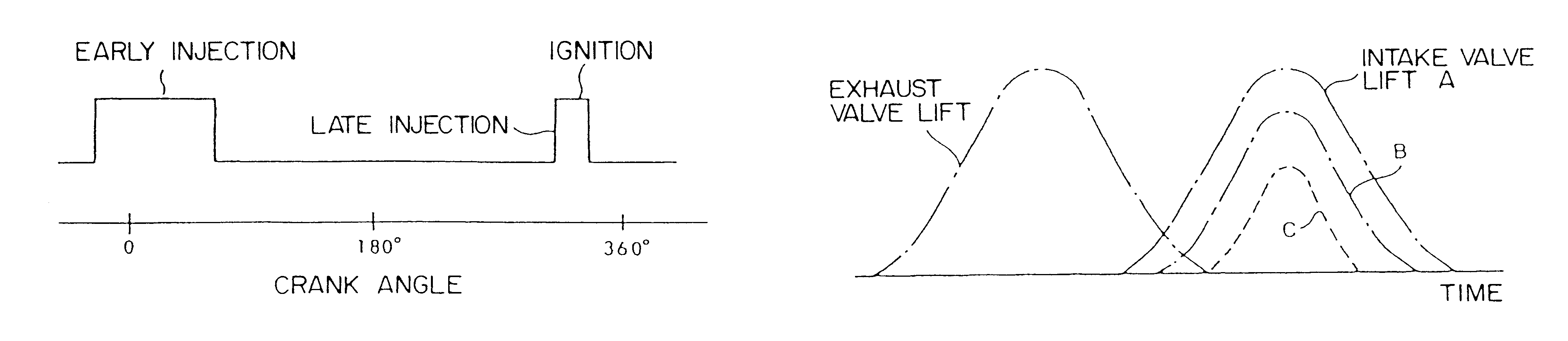
FIG. 4 shows a vertical cross-sectional view of a combustion chamber of a In this embodiment, a fuel injection valve 13 is projected into the combustion chamber 7, and an injection port is so formed that the fuel can spread widely within a cylinder. In this case, when the fuel is injected when a piston is lowered to a point near to a bottom dead center, the fuel impinges directly on a wall surface of the cylinder to form a wall flow. In this condition, a good combustion can not be expected. Therefore, where the injection valve injects a wide spray, the fuel need to be injected at such a timing that a cavity 24 is disposed near to an upper dead center, and that the fuel can be blown into the cavity 24. For example, the injection of the fuel can be effected a plurality of times in a divided manner, as shown in FIG. 5. An early injection is effected at a crank angle of nearly 0.degree. to form a uniform mixture. A combustion initiator is produced by a late injection effected at a timi...

third embodiment

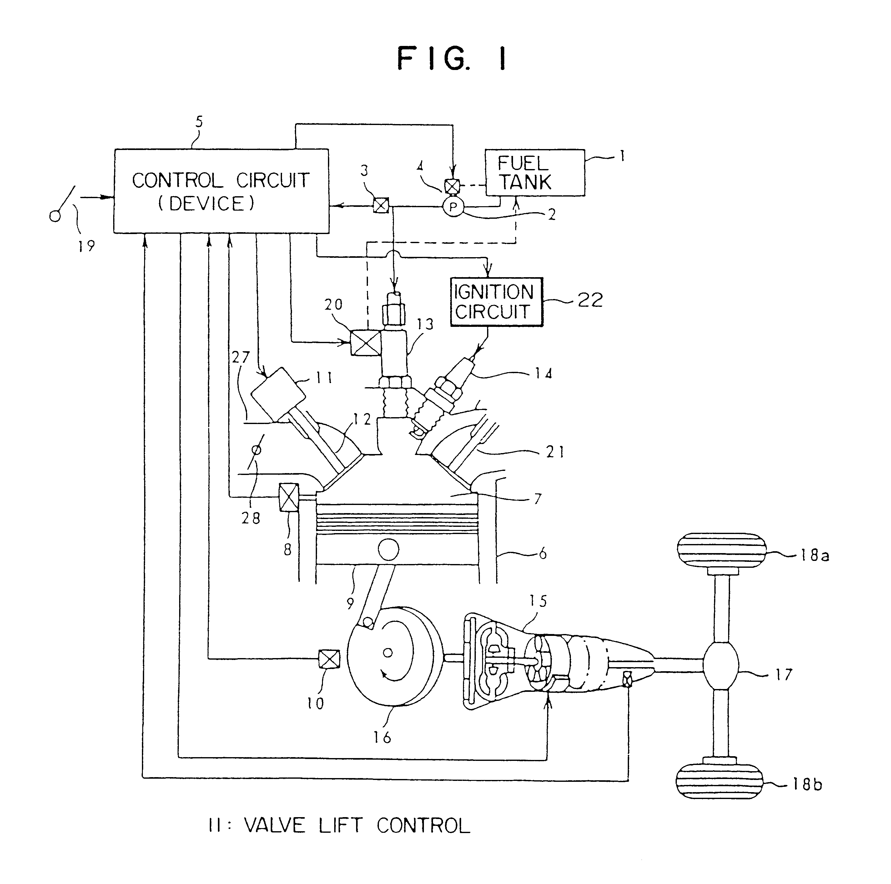
FIG. 9 shows the present invention. The air is controlled by a throttle valve 213, and is drawn into an engine through an intake manifold 214. A lift of an intake valve 208 can be changed by switching cams 203 of different shapes. The switching of the cams 203 is effected by switching rocker arms 210 by a hydraulic control valve 202. The hydraulic control valve 202 is operated, for example, by a solenoid. The degree of opening of the throttle valve 213 is controlled by a motor 212. A sensor 220 for detecting a pressure within a cylinder is mounted on the engine. An injection valve 204 for injecting the fuel directly into the cylinder is mounted on the engine. A sensor 205 for detecting the air / fuel ratio of exhaust gas is mounted on an exhaust pipe. A catalyzer is also provided in the exhaust pipe. Preferably, the catalyzer or catalyst is of a type which can remove NOx even when an excessive amount of oxygen is present. Also, function of a three-way catalyst, which can remove HC, CO...


PUM


Abstract

The engine disclosed features an engine cylinder provided with an air intake valve, an injector having a fuel injection port which is directed towards an interior of the engine cylinder, and a control unit which is connected to the air intake valve and to the injector, the control unit effecting changes in the air intake amount by controlling the degree of opening of the air intake valve, and, also, controls the air/fuel ratio by changing the amount of fuel supplied by the injector. The engine also has an exhaust valve in the engine cylinder such that the control unit controls the intake valve and the exhaust valve so that an opening period of the intake valve is overlapped with an opening period of the exhaust valve at least when the opening period of the intake valve is maximum. The period of the overlap is longer when a relatively large amount of air is required than when a relatively small amount of air is required. According to such a scheme, the amount of the air can be changed by the lift of the intake valve. By changing the lift, the overlap with an exhaust valve is also changed. During the high-output or power operation, the period of overlap between the exhaust valve and the intake valve is made longer. When engine torque decreases to a level lower than the target engine torque, the air amount is adjusted by the cam or the throttle valve.

Description

1. Field of the InventionThis invention relates generally to a spark-ignition internal combustion engine, and more particularly to an apparatus for and a method of controlling a spark-ignition internal combustion engine of the type in which fuel is injected directly into a cylinder.2. Related ArtThere is known a conventional system (Japanese Patent Unexamined Publication No. 2-153257) in which fuel is injected directly into a cylinder by use of the air pressure. A conventional diesel engine utilizes a stratified combustion, and therefore the maximum output or power is low although the fuel consumption under a partial load is enhanced. On the other hand, a conventional gasoline engine has a drawback that although the maximum output or power is high because of a premixture combustion, the fuel consumption under a partial load is worsened because of a pumping loss.It is an object of this invention to provide an apparatus for and a method of controlling an internal combustion engine, in...

Claims


Application Information

Patent Timeline
Patent Type & Authority Patents(United States)
IPC IPC(8): F02D37/00F01L9/04F02D33/00F02B17/00F02D29/02F01L13/00F02D41/14F02D37/02F02B23/10F02D41/30F02D41/38F02D41/34F02B19/00F02M69/04F02D41/02F02B19/12F01L1/26F02D11/10F02D13/02F02D41/40F02M45/00F02M45/02F02B75/12F02M25/07F02B75/00F16H61/14F16H61/02F16H61/00F01L9/20F02B3/06F16H61/04
CPCF01L1/267F01L13/0036F02B17/005F02B19/12F02B23/101F02D11/105F02D13/023F02D13/0261F02D29/02F02D33/00F02D35/023F02D37/02F02D41/0225F02D41/023F02D41/1475F02D41/149F02D41/1497F02D41/3029F02D41/307F02D41/3082F02D41/34F02D41/3809F02D41/3845F02D41/402F02M45/02F02M69/045F01L9/04Y10T477/677F01L2201/00F01L2800/00F02B3/06F02B2023/102F02B2023/108F02B2075/125F02B2275/40F02D41/1446F02D41/187F02D2041/001F02D2041/002F02D2041/389F02D2200/0602F02D2250/18F02F2001/241F02M25/0774F02M25/0777F02M2025/0759F02M2025/0761F16H61/0213F16H61/14F16H63/502F16H2061/0018Y02T10/125Y02T10/18Y02T10/44Y02T10/76Y02T10/12Y02T10/123Y02T10/42Y10T477/663Y10T477/68F02M2026/002F02M2026/003F02M26/55F02M26/57Y02T10/40F01L9/20F02D45/00
Inventor FUJIEDA, MAMORUNOGI, TOSHIHARUOYAMA, YOSHISHIGEOHSUGA, MINORUSHIRAISHI, TAKUYA
Owner HITACHI LTD
Why Eureka
Try Eureka