Subsonic aircraft with backswept wings and movable wing tip winglets

a technology of wing tip and winglet, which is applied in the direction of wing adjustment, aircraft components, influencers by generating vortices, etc., can solve the problems of reducing the safety risk of following, reducing the span width of aircraft wings equipped with such winglets, and achieving optimal reduction of induced flow resistance at one particular operation

Inactive Publication Date: 2002-02-12
DAIMLER CHRYSLER AEROSPACE AIRBUS
View PDF8 Cites 143 Cited by
  • Summary
  • Abstract
  • Description
  • Claims
  • Application Information

AI Technical Summary

Problems solved by technology

In this context, an optimal reduction of the induced flow resistance can only be achieved at one particular operating condition or point of the aircraft, because the individual winglets are not rotatable about an axis extending parallel to the aircraft lengthwise axis.
Furthermore, it is especially not possible to reduce the span width of the aircraft wings equipped with such winglets while the aircraft is parked at a ramp or jetway.
As a further disadvantage or limitation, a reduction of the safety risk for following aircraft is achieved only in the reduction of the induced drag.
The individual winglets are not torsionally warpable or twistable, or torsionally adjustable, which leads to a lower effectiveness than if the winglets were so torsionally twisted.
Further, in this known arrangement it is not possible to form large counter vortices.
The above described disadvantages also apply to the high lift wing arrangement known fr...

Method used


Image

  • Subsonic aircraft with backswept wings and movable wing tip winglets
  • Subsonic aircraft with backswept wings and movable wing tip winglets
  • Subsonic aircraft with backswept wings and movable wing tip winglets

Examples


Embodiment Construction

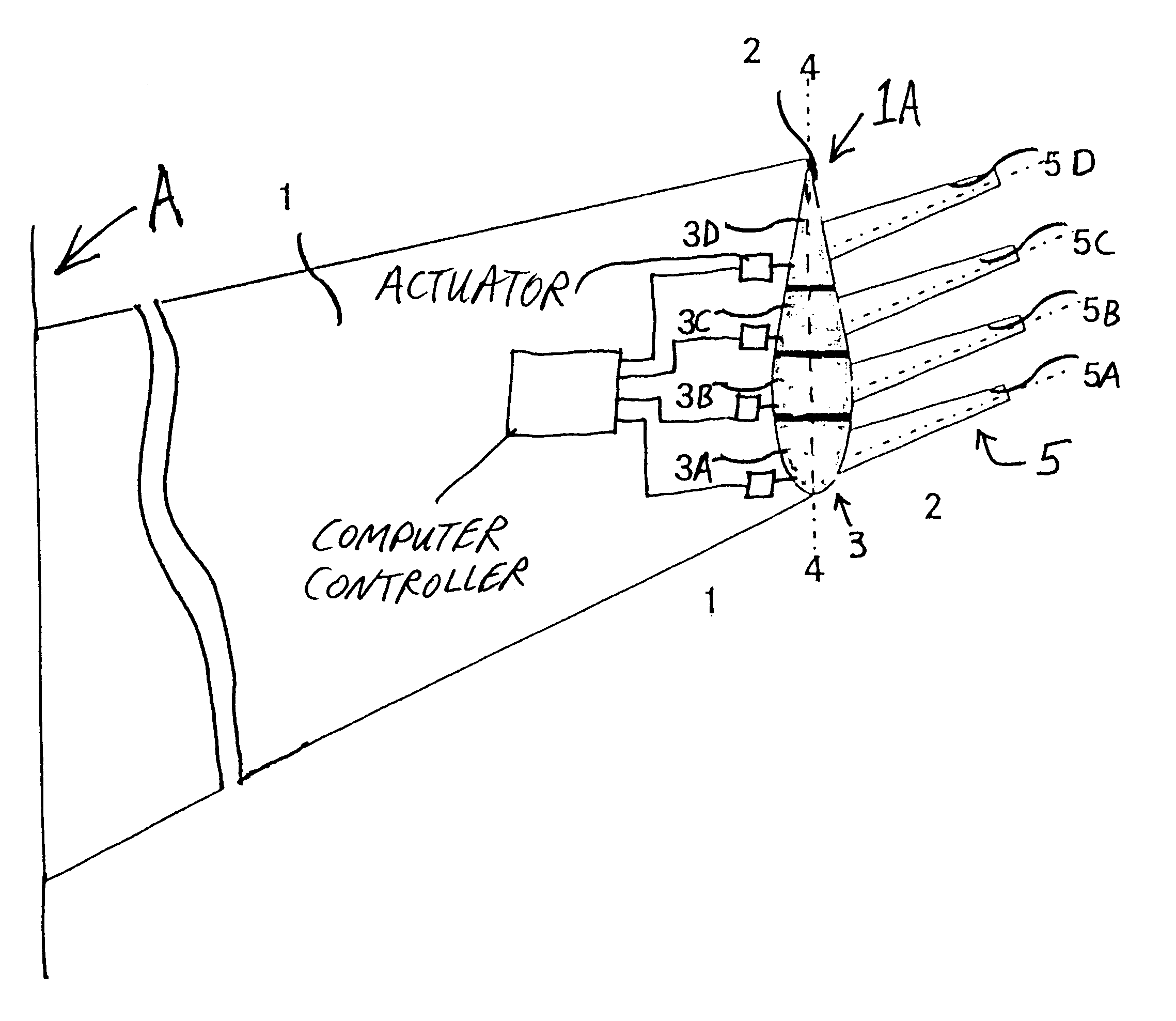
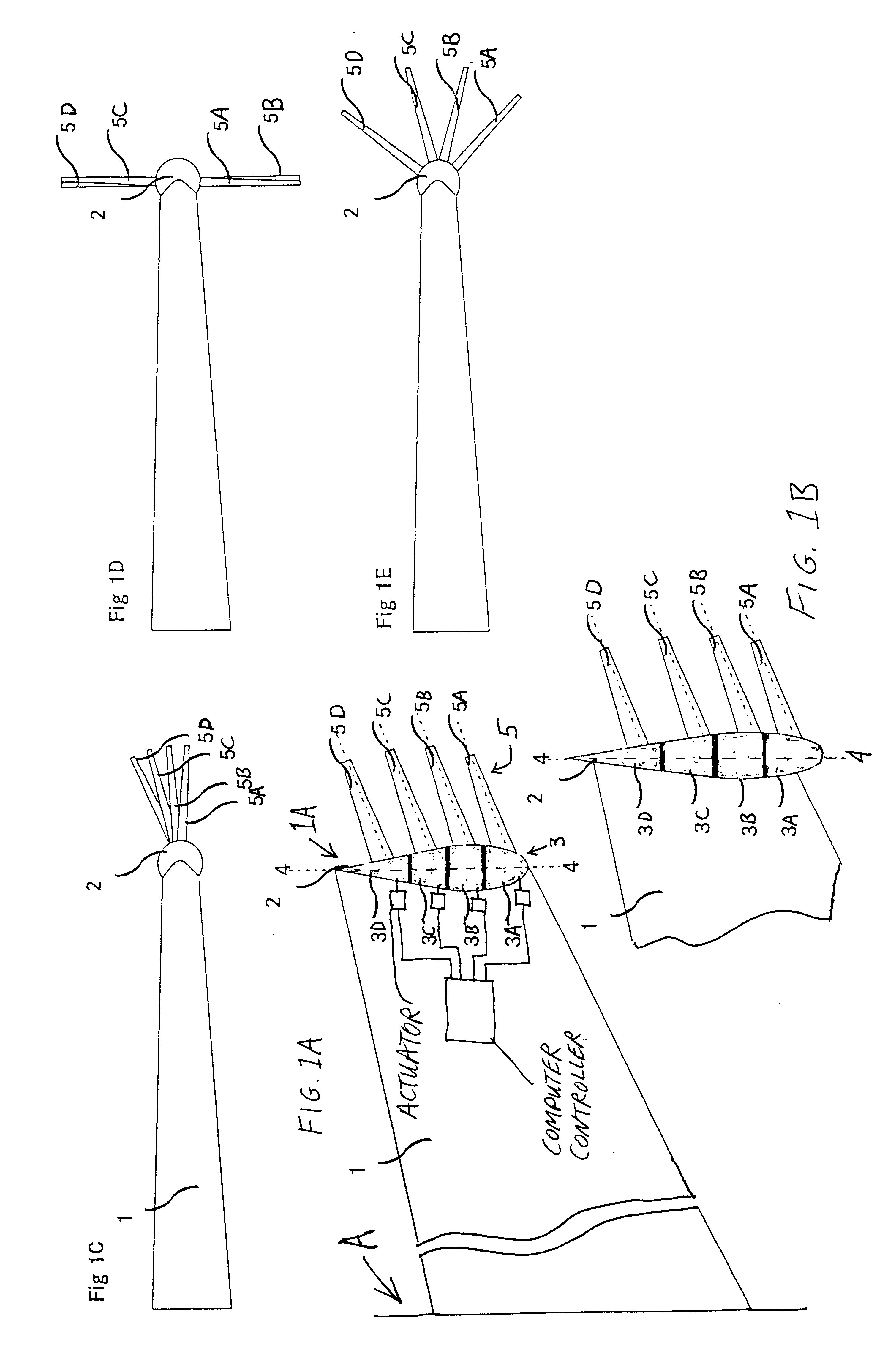
FIGS. 1A and 1B each merely schematically show a portion of a backswept wing 1 of an aircraft A. In FIG. 1A, the aircraft A is schematically indicated, whereby the wingspan length of the wing 1 has been significantly contracted for the sake of a compact schematic drawing. As shown in FIGS. 1A and 1B, a rotation body 2 is mounted at the wing tip 1A of the wing 1. The rotation body 2 overall has a streamlined shape, such as a generally recognized teardrop, torpedo, or bullet shape, with an optimized aerodynamic contour, whereby the maximum thickness of the rotation body 2 may correspond to or be greater than the thickness of the wing 1 at the wing tip 1A.

The length of the rotation body 2 in the aircraft longitudinal direction may correspond to the local wing profile length or chord length as shown in the embodiment of FIG. 1A, or may be greater than the local wing profile length or chord length of the wing 1 as shown in the embodiment of FIG. 1B. In other words, in the embodiment of F...


PUM


Abstract

A subsonic aircraft having backswept lifting wings is equipped with individually rotatable winglets at the wing tips thereof, in order to reduce drag during cruise flight, to minimize the dangers posed by wing tip vortices to following aircraft during take-off and landing, and to minimize the total wingspan during ground operations, with respective different positions of the winglets. A streamline-shaped rotation body made up of at least two individually rotatably supported rotation segments is mounted on the wing tip of each lifting wing. A respective winglet is mounted on each respective rotation segment. Each rotation segment with its associated winglet is individually rotatable about a rotation axis of the rotation body extending substantially parallel to the aircraft lengthwise axis. Thereby, each winglet is individually pivotable to any selected pivot angle relative to a horizontal plane extending through the rotation axis. Each winglet and its associated rotation segment is rotatable through an angular range between maximum end limits of at least +90° (vertically upward) and at least -90° (vertically downward) relative to the horizontal plane.

Description

PRIORITY CLAIMThis application is based on and claims the priority under 35 U.S.C. .sctn.119 of German Patent Application 199 26 832.0, filed on Jun. 12, 1999, the entire disclosure of which is incorporated herein by reference.The invention relates to a subsonic aircraft preferably having backswept wings, whereby the tips of the lifting wings are equipped with so-called winglets for reducing the induced flow resistance or drag during cruise flight and especially also for minimizing the dangers posed by wing tip vortices to aircraft is following an aircraft equipped with such winglets.BACKGROUND INFORMATIONIn order to achieve the desired reduction of the induced flow resistance or drag during cruise flight, various different fixed winglet forms, of which the arrangement cannot be adjusted or moved during flight, have become known in the art. For example, the following general type of winglets are known; winglets that are suggestive of end disks secured to the wing tips; simple or sin...

Claims


Application Information

Patent Timeline
IPC IPC(8): B64C23/00B64C23/06
CPCB64C23/065Y02T50/164B64C23/076Y02T50/10
Inventor BRIX, WOLFGANG
Owner DAIMLER CHRYSLER AEROSPACE AIRBUS
Why Eureka
Try Eureka