Suction muffler and hermetic compressor

a compressor and suction muffler technology, applied in the direction of machines/engines, liquid fuel engines, positive displacement liquid engines, etc., can solve the problems of deteriorating the refrigeration capacity of the refrigeration cycle, affecting the operation of the compressor, and the pressure of the refrigerant gas inside the compression chamber may not reach a predetermined level

Inactive Publication Date: 2002-03-26
PANASONIC APPLIANCES REFRIGERATION DEVICES SINGAPORE
View PDF4 Cites 12 Cited by
  • Summary
  • Abstract
  • Description
  • Claims
  • Application Information

AI Technical Summary

Benefits of technology

The present invention is intended to provide a compressor having a suction muffler assembled by mutually and stably joining the portions thereof made of a thermoplastic synthetic resin at uniform welding strength without causing fins.
With this configuration, the volume of the melted portion incorporating the conductor with the holes is larger than the volume of the melted portion incorporating a conductor with no hole by the volume of the spaces inside the holes. In addition, the sectional area of the melted portion in parallel with the joining faces is made larger, thereby ensuring higher welding strength.

Problems solved by technology

If the mist-like lubrication oil is directly sucked into the compression chamber, the lubrication oil may attach to the suction valve or the discharge valve, thereby deteriorating their functions.
Furthermore, if the lubrication oil is discharged to the refrigeration cycle through the discharge pipe 10, the lubrication oil may attach to various portions in the refrigeration cycle, thereby deteriorating the refrigeration capability of the refrigeration cycle.
If this occurs, the pressure of the refrigerant gas pressurized inside the compression chamber may not reach a predetermined level.
However, the portions formed by injection forming a synthetic resin generally have warps.
If a large amount of lubrication oil enters the suction muffler from the gap and accumulates inside the compression chamber, the lubrication oil inside the compression chamber excessively transmits the pressing force of the piston, thereby causing a danger of breaking the suction valve and the discharge valve.
In addition, the lubrication oil circulates in the refrigeration cycle outside the compressor, and stagnates at the evaporator, thereby causing improper refrigeration.
If the various portions constituting the suction muffler are misaligned eventually as the result of the widened gap, there is a possibility of causing large abnormal noise.
However, in these methods, it is inevitable that the amount of the melted resin becomes excessive at some portions.
If the broken pieces of the fins drop into the suction muffler during the operation of the compressor and then enters the compressor, they are caught between the piston and the partition wall of the cylinder, thereby causing a danger of preventing the piston from reciprocating smoothly.
Alternatively, they are caught at the suction valve or the discharge valve, thereby causing a danger of damaging the hermetic sealing of the compression chamber.
Both of these cases cause a problem of hindering the pressure of the refrigerant gas from rising to a predetermined value.
However, as long as the heating is carried out by vibration as described above, even if the vibration welding is used, it is impossible to eliminate the nonuniformity in the heating temperature owing to the unevenness on the joining faces.
Furthermore, the vibration welding has the following problems.
If the frequency is raised excessively during the vibration welding, the whole joining faces cannot vibrate uniformly.
Therefore, a long time is required for the welding, and it is difficult to adjust the time for the welding.

Method used


Image

  • Suction muffler and hermetic compressor
  • Suction muffler and hermetic compressor
  • Suction muffler and hermetic compressor

Examples


embodiment 1

With the above-mentioned configuration, the compressor of the embodiment 1 raises the pressure of the refrigerant gas and supplies the high-pressure refrigerant gas to an external refrigeration cycle.

When the electric motor 3 is driven, the piston 5 is reciprocated inside the cylinder 4 by the crank portion 12. The space inside the compression chamber 21 of the cylinder 4 is changed periodically in accordance with the reciprocation. The pressure of the refrigerant gas inside the compression chamber 21 lowers while the space inside the compression chamber 21 increases. At this time, the suction valve is opened by the pressure difference between the pressure at the outside space 22 of the compression chamber 21 and the pressure inside the compression chamber 21 thereby to suck the refrigerant gas discharged from the inside of the suction muffler 8 through the discharge outlet 8b thereof. On the other hand, the pressure of the refrigerant gas inside the compression chamber 21 rises whi...

embodiment 2

Embodiment 2 differs from the embodiment 1 only in the shape of the joint portion of the suction muffler 8. Portions other than the joint portion are the same as those of the embodiment 1, and their descriptions are omitted.

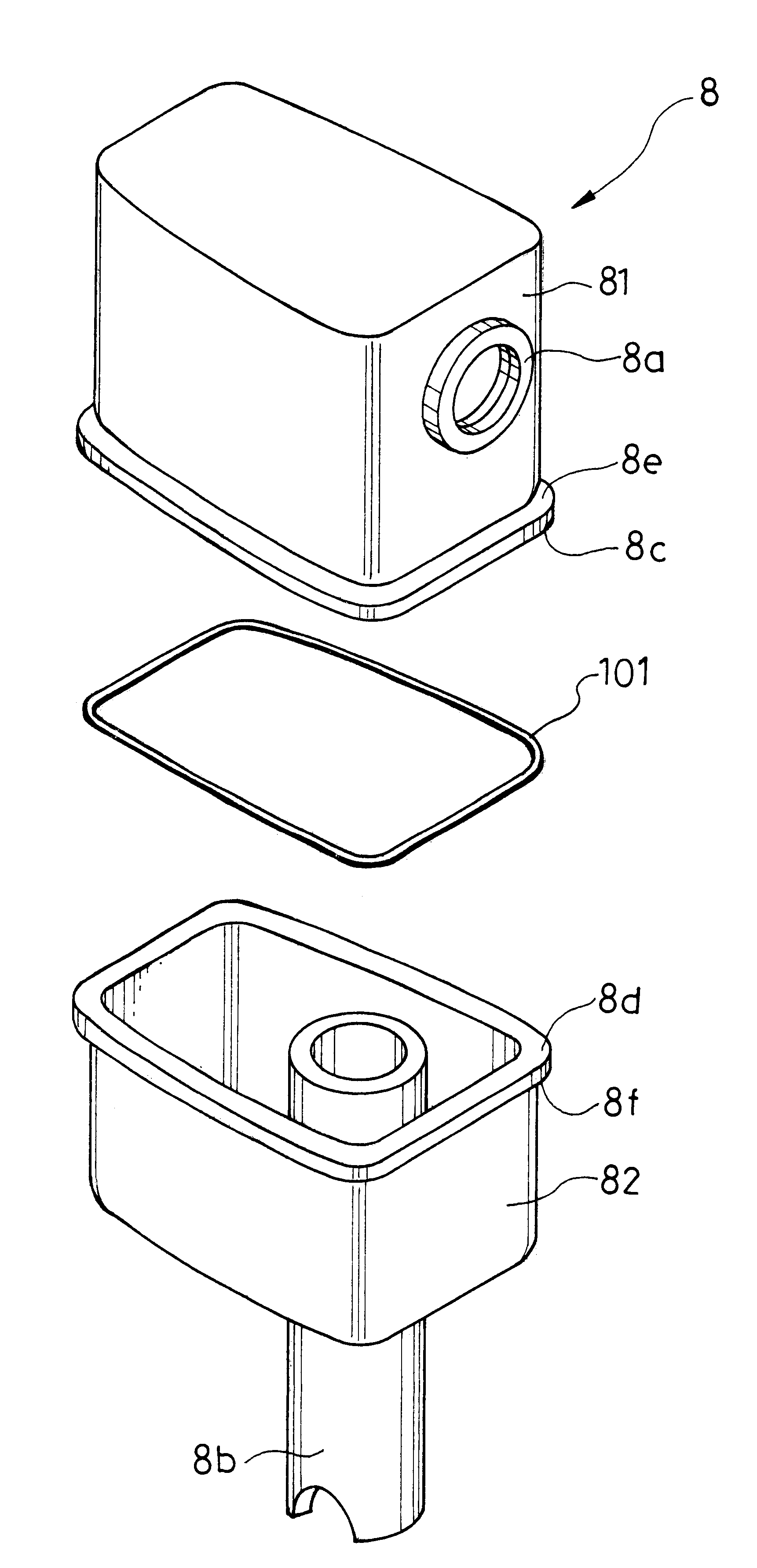
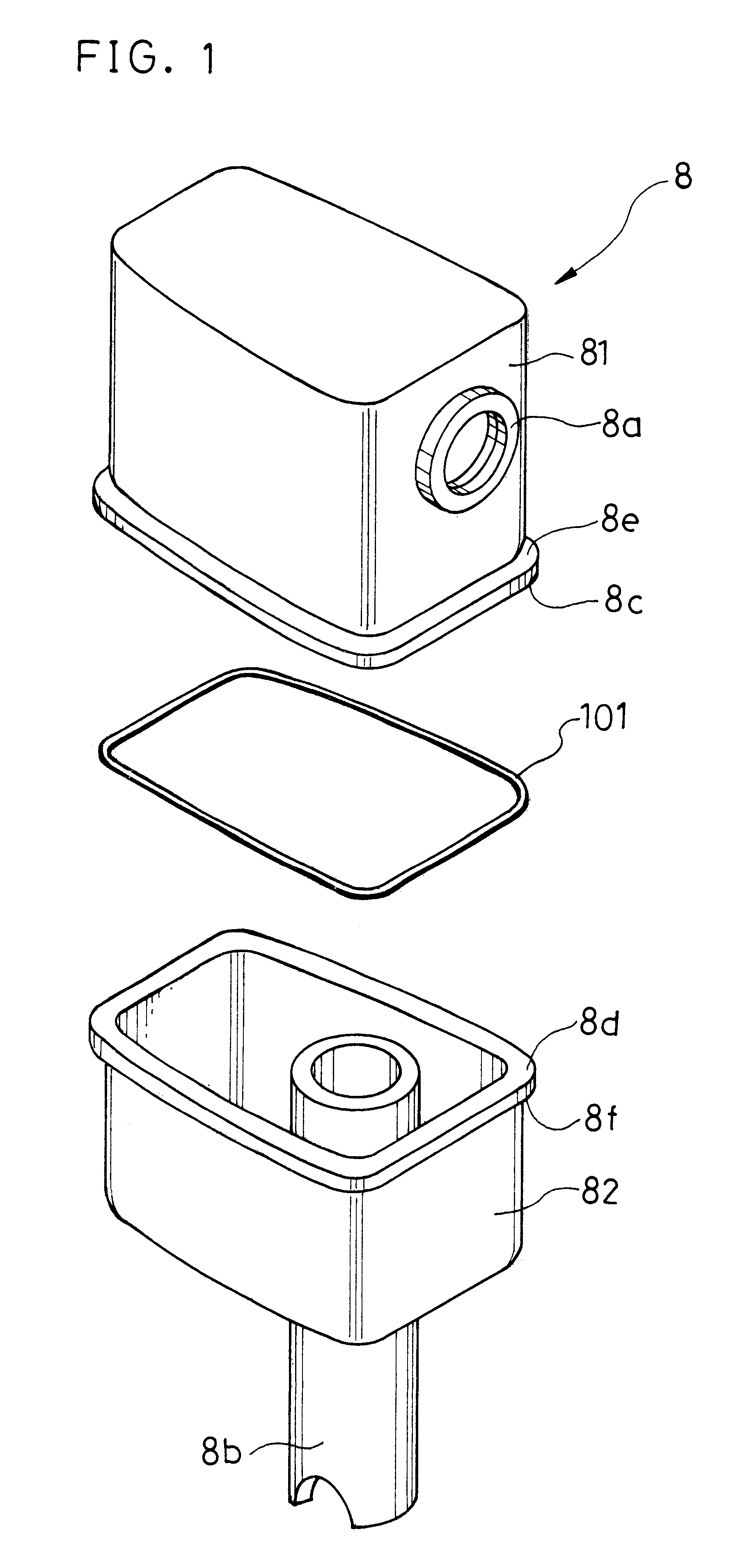
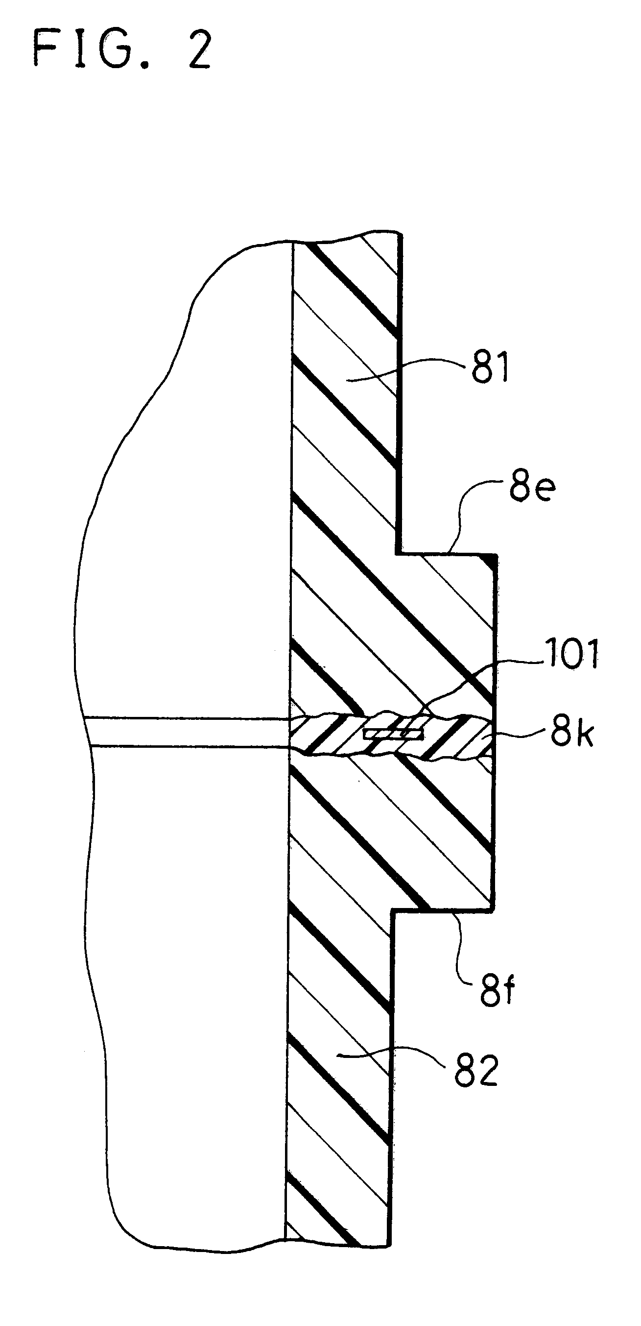
FIG. 5 is an exploded perspective view showing the suction muffler 8 of the embodiment 2. As shown in FIG. 5, the suction muffler 8 comprises two portions 81 and 82 and a conductor 102 held between the two portions. The portions 81 and 82 are each formed by injection forming PBT, and each have a substantial shape of a rectangle measuring about 60 mm in width, about 25 mm in thickness and about 70 mm in height. A projection 8g is formed along the central portion of the joining face 8c of the upper portion 81. On the other hand, a groove 8h is formed along the central portion of the joining face 8d of the lower portion 82. The vertical sectional shapes of the projection 8g and the groove 8h are rectangular, and they are substantially identical to each other in size...


PUM

PropertyMeasurementUnit
timeaaaaaaaaaa
heightaaaaaaaaaa
heightaaaaaaaaaa

Abstract

The present invention provides a suction muffler comprising component portions formed by injection forming a thermoplastic synthetic resin and joined to each other by induction welding, and also provides a hermetic compressor including the suction muffler. The suction muffler having this configuration is superior to conventional suction mufflers having joint portions joined by ultrasonic welding and vibration welding in the uniformity of the welding strength at the whole joint portion thereof and in minimizing the occurrence of fins.

Description

The present invention relates to a hermetic compressor (hereinafter referred to as a compressor) for use with electric refrigerators, air conditioners and the like, and more particularly to a suction muffler included in the compressor.The principle of refrigeration in electric refrigerators, air conditioners and the like is described below briefly. A compressor is used to compress a refrigerant gas to raise its pressure. The high-pressure refrigerant gas is cooled and liquefied. When the liquefied gas vaporizes in an evaporator, the gas extracts vaporization heat from the air inside a refrigerator or a room. The evaporated refrigerant gas is returned to the compressor. The above-mentioned operation is repeated, thereby lowering the temperature of the air inside the refrigerator or the room. In the present invention, the above-mentioned change of the refrigerant from being discharged from the compressor to returning to the compressor is referred to as a refrigeration cycle.Refrigeran...

Claims


Application Information

Patent Timeline
Patent Type & Authority Patents(United States)
IPC IPC(8): F04B39/00F16B5/08
CPCF04B39/0072Y10S417/902B29C65/08B29C65/3644B29C65/3668B29C65/3676B29C66/124B29C66/1312B29C66/30223B29C66/322B29C66/54B29C66/73921B29C66/83221B29C65/0618B29C66/71B29C65/362B29C66/24244B29C66/24243B29C66/8161B29K2067/006F04B39/00
Inventor IDE, TERUMASA
Owner PANASONIC APPLIANCES REFRIGERATION DEVICES SINGAPORE
Why Eureka
Try Eureka