Electrostatic precipitator slow pulse generating circuit

a technology of electrostatic precipitator and slow pulse, which is applied in the direction of electric supply techniques, instruments, process and machine control, etc., can solve the problems of limited success

Inactive Publication Date: 2002-03-26
ALPHA OMEGA POWER TECH L L C
View PDF17 Cites 144 Cited by
  • Summary
  • Abstract
  • Description
  • Claims
  • Application Information

AI Technical Summary

Benefits of technology

A primary advantage of the present invention is that a voltage pulse is produced on the electrostatic precipitator load, having a slower rise-time, and which aids in eliminating back-corona on the ESP plates.

Problems solved by technology

In the United States numerous systems have been investigated over the years with limited success due to overall system costs and reliability.

Method used


Image

  • Electrostatic precipitator slow pulse generating circuit
  • Electrostatic precipitator slow pulse generating circuit
  • Electrostatic precipitator slow pulse generating circuit

Examples


first embodiment

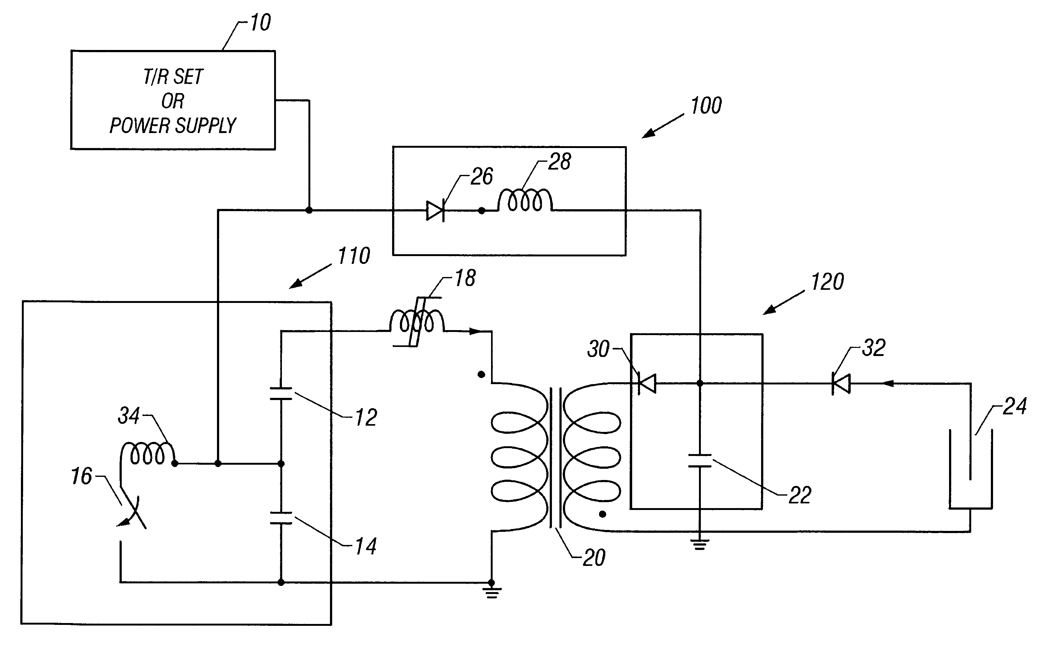
Attention is now turned to the figures. The first embodiment is shown in FIG. 1. This embodiment allows for the larger capacitance to be switched to load 24 where it can maintain an average electric field. The means for charging the means for producing pulsed voltage can be either existing T / R sets, or a power supply, 10 at a rate between 10 Hz and 10 kHz. Other charging means can also be used in each embodiment.

The means for producing pulsed voltage in this embodiment is an inversion circuit. Many types of inversion circuits could be used in this and other embodiments, and would be apparent to those skilled in the art. In this embodiment, circuit operation is as follows. First, inversion circuit first primary storage capacitor 12 and inversion circuit second primary storage capacitor 14 are charged to a preset voltage. Once storage capacitors 12 and 14 have been charged, primary switch 16 is triggered and closes. When switch 16 closes, the voltage on second storage capacitor 14 rev...

second embodiment

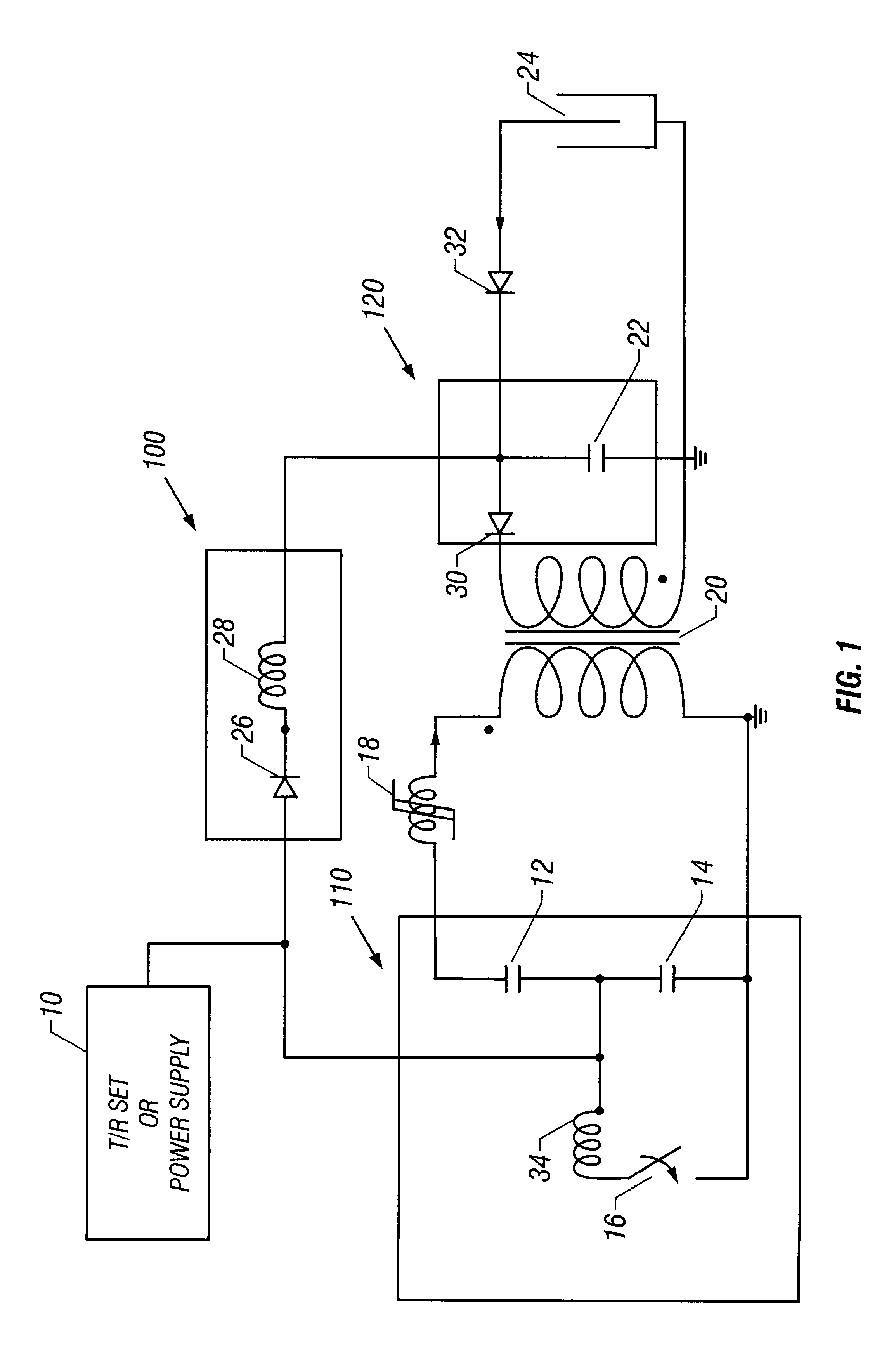
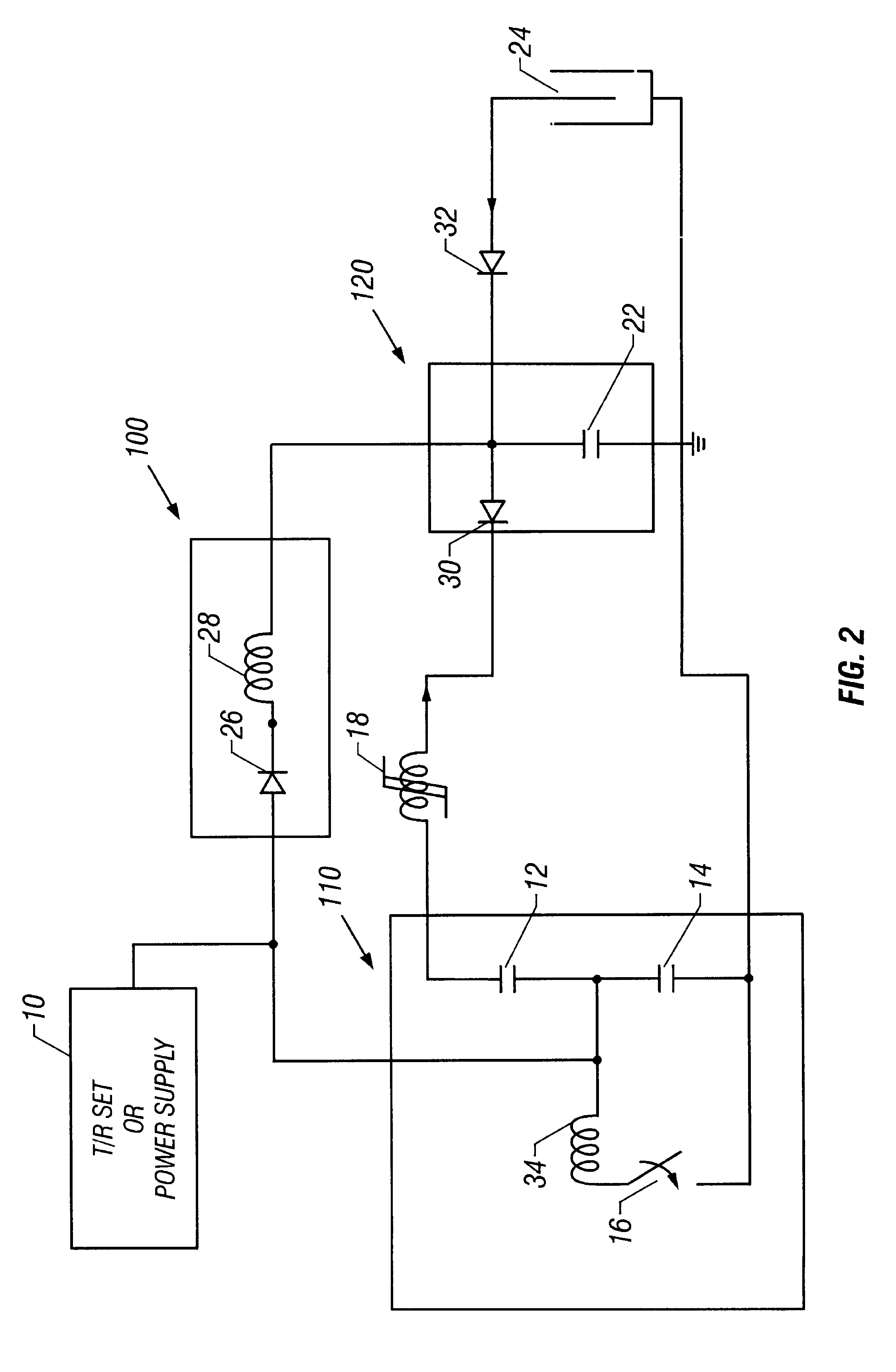
In a second embodiment, the present invention is used without transformer 20 (shown in FIG. 1) as shown in FIG. 2. In this embodiment, the circuit operates as follows. First, inversion circuit first primary storage capacitor 12 and inversion circuit second primary storage capacitor 14 are charged to one-half the desired load voltage. Once capacitors 12 and 14 have been charged, primary switch 16 is triggered and closes. When switch 16 closes, the voltage on second primary storage capacitor 14 reverses and the voltage on first magnetic switch 18 is doubled and first magnetic switch 18 saturates. When magnetic switch 18 saturates, the energy from capacitors 12 and 14 is transferred to load matching capacitor 22. Capacitor 22 is charged along with load 24. The voltage at this point is between 20 kV and 100 kV. Any unused energy that does not get utilized by load 24 is transferred back to inversion circuit primary storage capacitors 12 and 14 through energy recovery circuitry 100 made u...

third embodiment

In the present invention, an alternative energy recovery circuit is used as shown in FIG. 3 at 100 and 102. This energy recovery circuit allows for larger capacitance to be switched to load 24 where it can maintain an average electric field. As in previous embodiments, the system can be charged with existing T / R sets, or a power supply, 10 at a rate between 10 Hz and 10 kHz. Energy recovery storage capacitor 38 is used on the output of T / R set (or power supply) 10 with a series charge element 40 which can be either a series charge resistor or an inductor.

Circuit operation is as follows. First, inversion circuit first primary storage capacitor 12 and inversion circuit second primary storage capacitor 14 are charged to a preset voltage. Once primary storage capacitors 12 and 14 have been charged, primary switch 16 is triggered and closes. When primary switch 16 closes, the voltage on second primary storage capacitor 14 reverses and the voltage on first magnetic switch 18 is doubled, a...


PUM


Abstract

An apparatus and method for generating slow rise-time, high voltage electrical pulses to a load, preferably using an existing transformer / rectifier set or power supply to charge an inversion or high voltage switching circuit to produce the pulsed voltage. An energy recovery circuit (100, 102) is used to return unused energy from the load (24) back to the means for producing pulsed voltage (110, 130). A load matching circuit (120) uses a blocking diode and a capacitor for charging the load. An additional blocking diode (32) inhibits load voltage discharge back through the slow pulse generating circuit. A transformer (20) can be used to step-up voltage from the inversion circuit, or high voltage switching circuit, to the load. One or more magnetic switch stages are used to transfer energy from the inversion circuit, or high voltage switching circuit, to the load matching circuit. A fire-on voltage controller (66) triggers the inversion or high voltage switching circuit.

Description

1. Field of the Invention (Technical Field)The present invention relates to circuits for generating high voltage electrical pulses.2. Background ArtWith the thrust to maintain a clean environment, the need for better particulate control in industrial processes is needed. Electrostatic precipitators are one of the most widely used methods of collecting particulate matter in flue gas systems. In general, the systems are comprised of sets of collecting plates which are usually at ground potential, high voltage electrodes, and a set of power supplies which delivers the high voltage to the electrodes. The high voltage electrode is made up of either a thin wire running the length of the collecting plates or a rigid electrode.The majority of the power supplies for the systems are made up of transformer / rectifier (T / R) sets. The T / R sets provide unfiltered, rectified high voltage (40 kV-80 kV) DC to the electrodes. It has been shown that better collection efficiency can be achieved by apply...

Claims


Application Information

Patent Timeline
Patent Type & Authority Patents(United States)
IPC IPC(8): B03C3/66
CPCB03C3/66Y10S323/903
Inventor CRAVEY, WILLIAM RAY
Owner ALPHA OMEGA POWER TECH L L C
Why Eureka
Try Eureka