Multipath propagation detection and avoidance method and system

a detection method and propagation detection technology, applied in direction finders using radio waves, instruments, reradiation, etc., can solve problems such as introducing errors in position and attitude determination, and the accuracy of attitude determination techniques that have not achieved the accuracy predicted, and achieve the effect of suppressing errors

Inactive Publication Date: 2002-03-26
CHARLES STARK DRAPER LABORATORY
View PDF3 Cites 21 Cited by
  • Summary
  • Abstract
  • Description
  • Claims
  • Application Information

AI Technical Summary

Benefits of technology

It is therefore an object of this invention to provide a multipath detection method and a syste

Problems solved by technology

However, attitude determination techniques have not achieved the accuracy predicted based solely on measurement noise considerations.
The widely held belief is that multipath propagation is the cause of the shortfall.
However, multipath propagation occurs when

Method used


Image

  • Multipath propagation detection and avoidance method and system
  • Multipath propagation detection and avoidance method and system
  • Multipath propagation detection and avoidance method and system

Examples


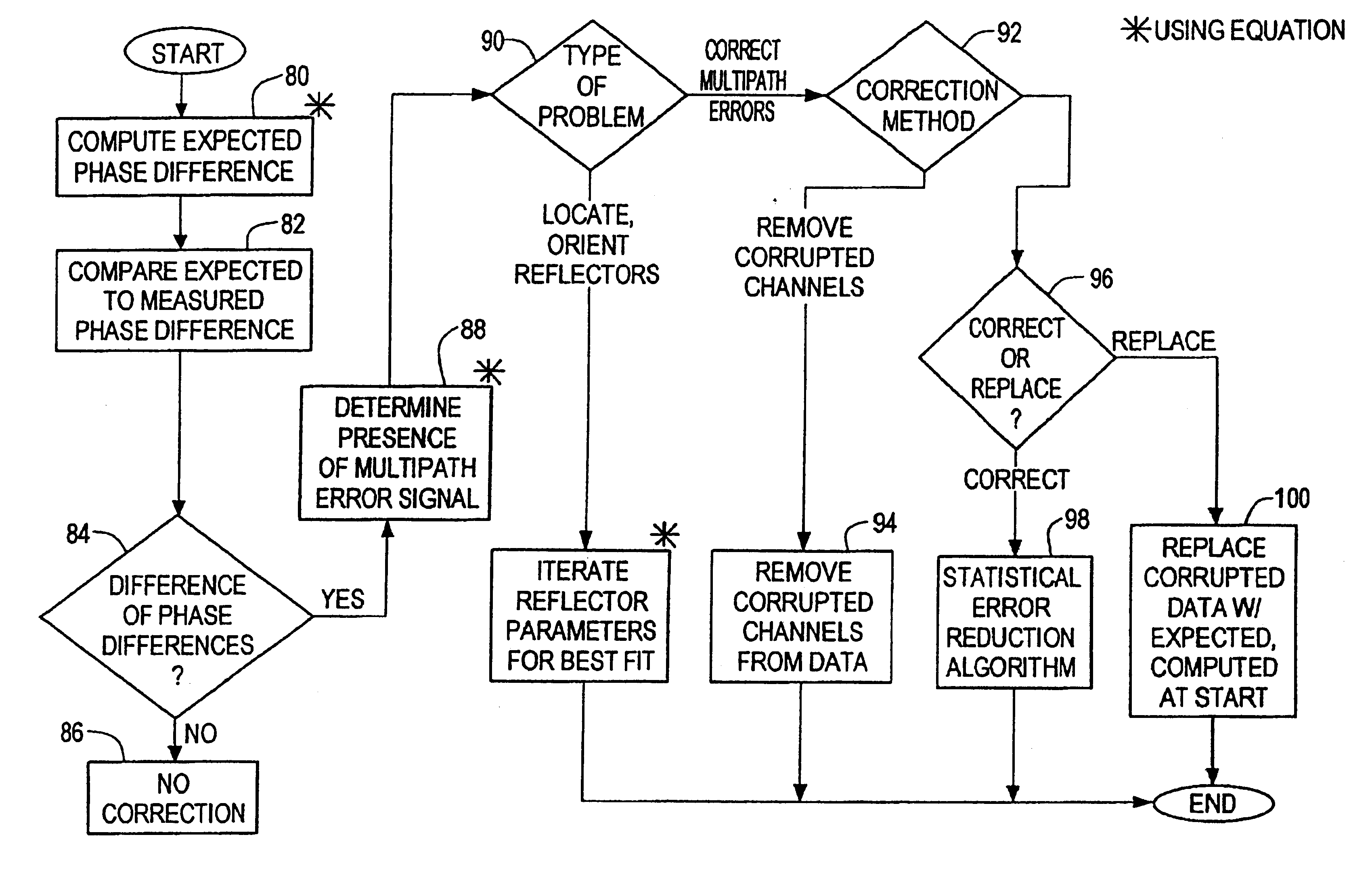
Embodiment Construction

Other objects, features and advantages will occur to those skilled in the art from the following description of a preferred embodiment and the accompanying drawings, in which:

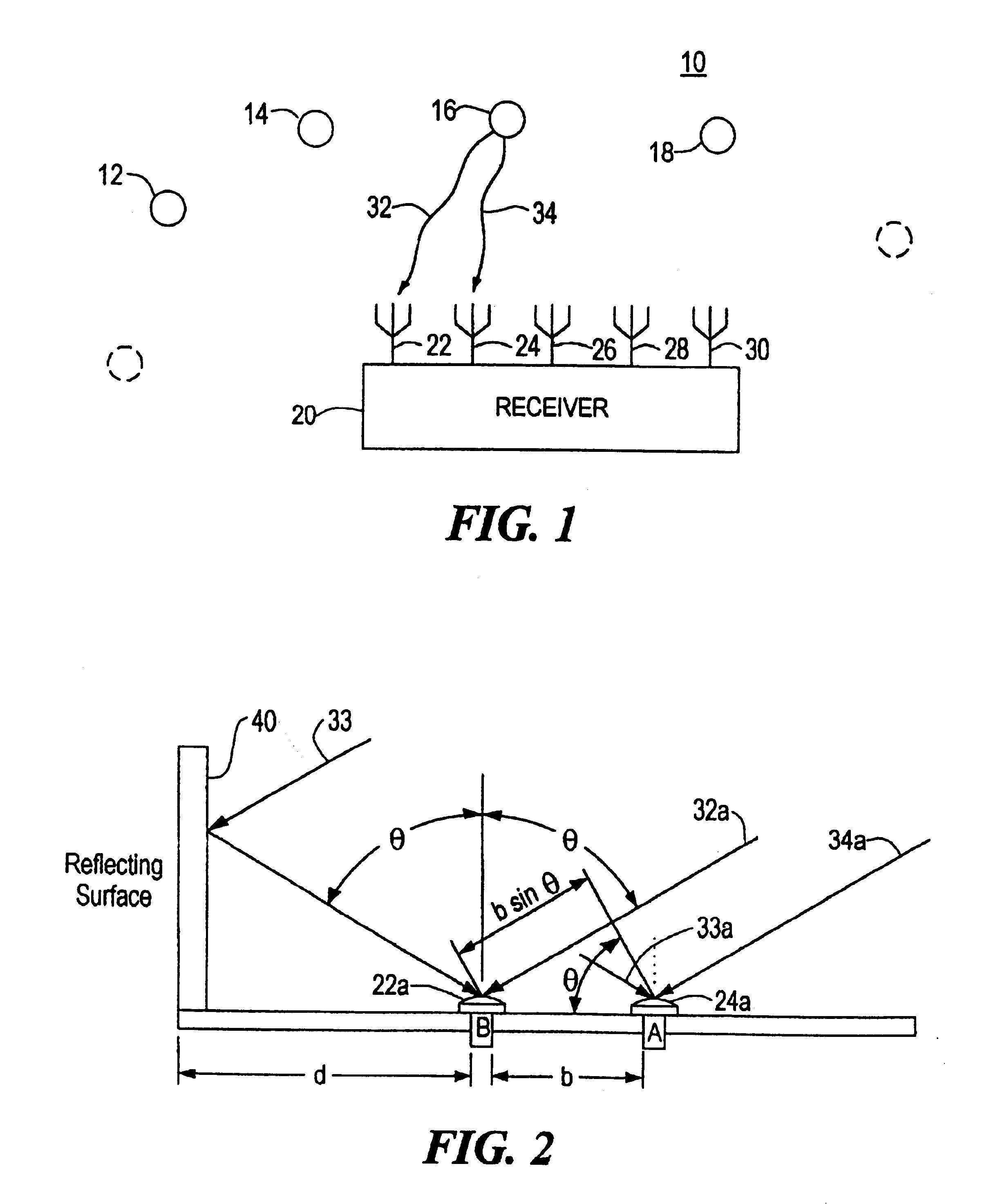
FIG. 1 is a schematic diagram of a GPS system which may use the multipath error detection method according to this invention;

FIG. 2 is a schematic ray diagram showing the conditions which cause multipath error;

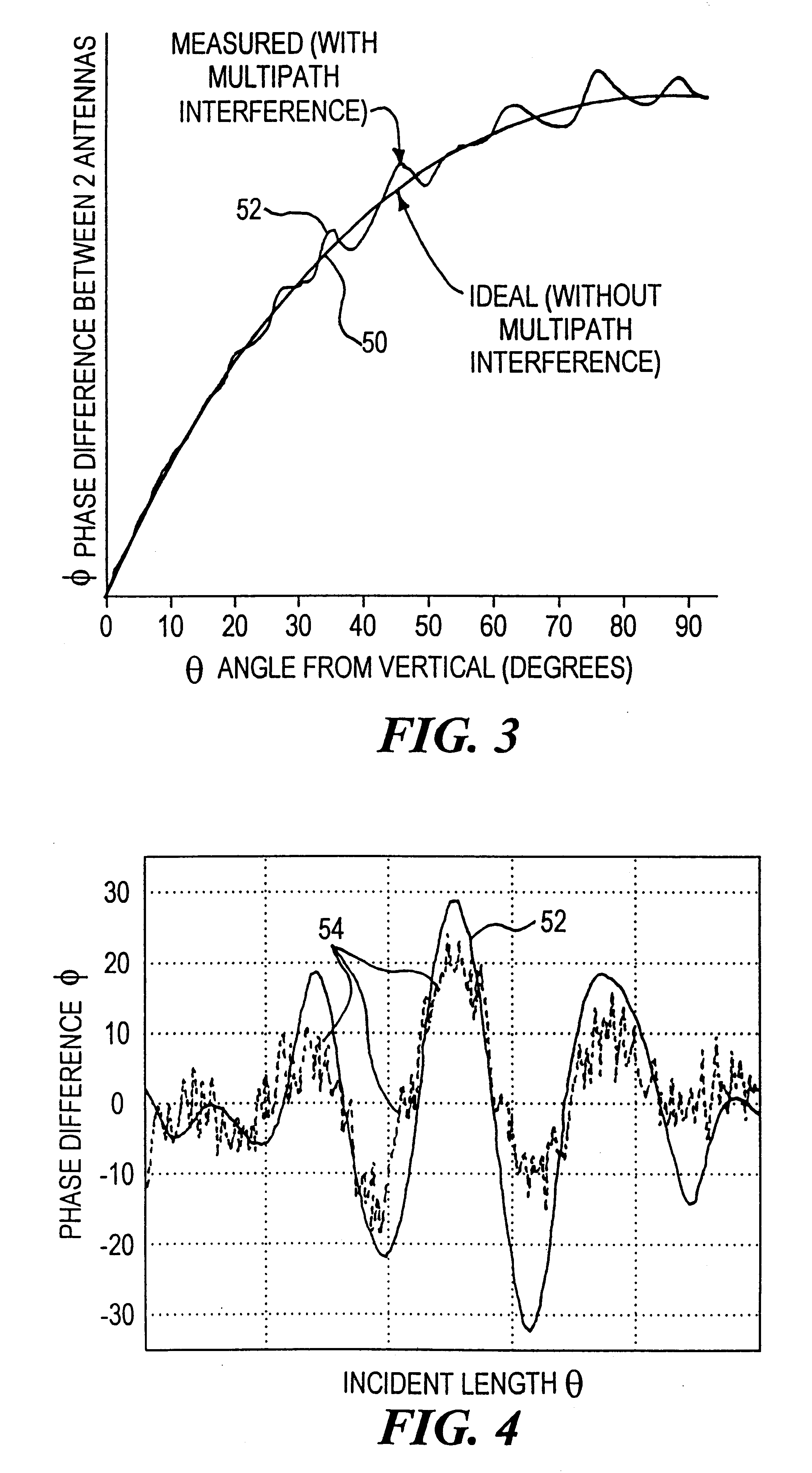
FIG. 3 illustrates the variation of phase difference between the two antennas with respect to the angle of incoming radiation ideally and with multipath error or interference;

FIG. 4 is an enlarged detail view of a computed multipath error signature superimposed on the multipath error data;

FIG. 5 is a schematic diagram showing the variables used in computing phase difference from the ephemeris and from determining the presence of a multipath error signal in the carrier signal;

FIG. 6 is a schematic block diagram of a multipath error detection system according to this invention used in a GPS environment;

FIG....


PUM


Abstract

Multipath propagation detection can be accomplished using first and second spaced antennas which receive a carrier signal from a moving radiation source and produce a carrier phase difference representative of the location of the source; a difference signal representative of the difference between the measured carrier phase difference and a predetermined phase difference for the source in that location is generated; and the presence of multipath distortion in that difference signal is determined. Furthermore, when a multiplicity of source signals are tracked as in reception of navigation signals from the Global Positioning Satellite System, the receiver may be programmed to eliminate or suppress errors arising from measurements that have been distorted by multipath propagation.

Description

This invention relates to a multipath detection and avoidance method and system, and more particularly to such a method and system for identifying multipath errors from a moving radiation source such as a GPS satellite and eliminating their effect on the performance of the receiver.BACKGROUND OF INVENTIONThe global positioning system (GPS) employs a GPS receiver responsive to the signals from a number of GPS satellites to determine the position of the receiver which may be borne by a person, airplane, missile, boat, car or other object. In more advanced applications the GPS may be used to determine not just the position but the attitude (e.g., the spatial orientation) of an object. For example, satellite carrier phase measurements from a plurality of antennas placed on the body, wings and tail, of an airplane can be processed by interferometric phase comparison to determine the roll, pitch and yaw of an airplane. However, attitude determination techniques have not achieved the accur...

Claims


Application Information

Patent Timeline
IPC IPC(8): G01S1/00H04B1/707G01S1/04G01S3/14G01S3/48
CPCG01S19/22G01S13/003G01S3/48G01S19/36
Inventor GREENSPAN, RICHARD L.MULLEN, FRANK E.
Owner CHARLES STARK DRAPER LABORATORY
Why Eureka
Try Eureka