Vertical comb drive actuated deformable mirror device and method

a mirror device and comb drive technology, applied in the field of adaptive optics, can solve the problems of limiting the resolution of microscopes, endoscopes, optical imaging systems, and star twinkleing and distant objects, and astronomical turbulence has frustrated astronomers

Inactive Publication Date: 2002-05-07
MEMS OPTICAL
View PDF3 Cites 297 Cited by
  • Summary
  • Abstract
  • Description
  • Claims
  • Application Information

AI Technical Summary

Problems solved by technology

Atmospheric turbulence has frustrated astronomers ever since telescopes were invented.
Atmospheric turbulence introduces aberrations on the wavefront of visible light, causing stars to twinkle and distant objects to shimmer.
Atmospheric turbulence also limits the resolution of microscopes, endoscopes, and other optical imaging systems.
While many adaptive optics systems are currently being used, they suffer from many shortcomings.
Current systems are typically complex, expensive, unreliable and difficult to maintain, thus putting them out of reach of amateur astronomers or commercial users.
Current adaptive optics systems are also very heavy and operate at relatively slow speed making them unsuitable for airborne applications where the fluctuating wavefront distortions move past the aperture at a much faster rate than stationary systems.
The primary obstacles to wider use of adaptive optics systems are cost, complexity, and reliability.
Current laser communications have limited range due to atmospheric distortions that cause beam bending and scatter energy from the beam.
Such sectioning can be achieved with confocal imaging in principle but current CSLOs do not tap the potential of confocal imaging because the retinal image quality is too poor.
In current technology, the deformable mirror is also the most expensive component of the adaptive optical system.
However, current LCD devices suffer from limited fill factor, limited bandwidth, and inadequate dynamic range.
Bandwidth limitations will preclude the use of LCD's for airborne or missile applications.
However, current SPZT devices suffer from high current operation, significant actuator nonuniformity, relatively high power dissipation, and moderate hysteresis effect.
Moreover, these devices are relatively expensive when compared to liquid crystals or MEMS devices.
Unfortunately the current designs do not produce the vertical displacements necessary for use in an optical system.

Method used


Image

  • Vertical comb drive actuated deformable mirror device and method
  • Vertical comb drive actuated deformable mirror device and method
  • Vertical comb drive actuated deformable mirror device and method

Examples


Embodiment Construction

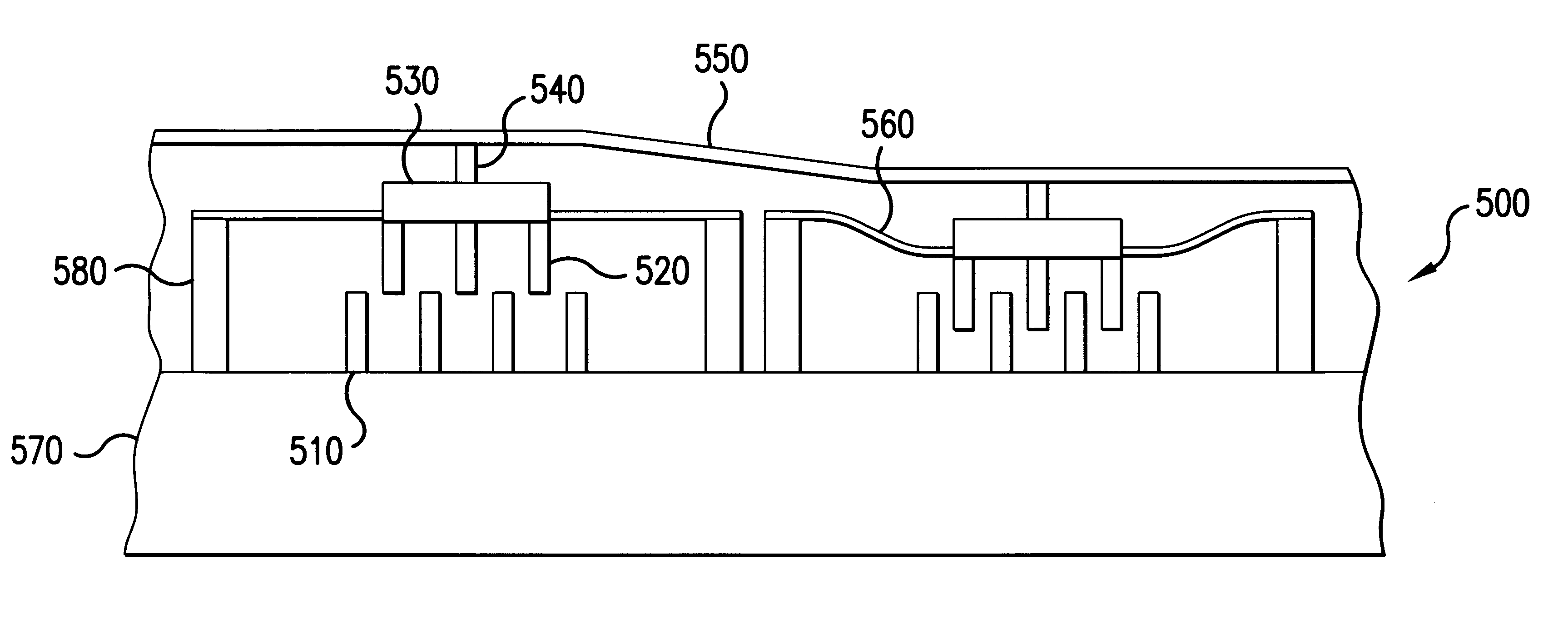
As noted above, typical MEMS have been based on electrostatic parallel plate capacitor actuators. The separation between the plate determines the amount of stroke available, but an increase in the separation increase the voltage required to deform the mirror. Thus, an increase in the stroke invariably increases the voltage. Further, since this separation between the plates is changing throughout the stroke, the response of the deformable mirror to the applied voltage is nonlinear. Electrostatic comb drives have been demonstrated to produce a large stroke and linear operation, but do not produce the vertical displacement required for use in deformable mirror applications.

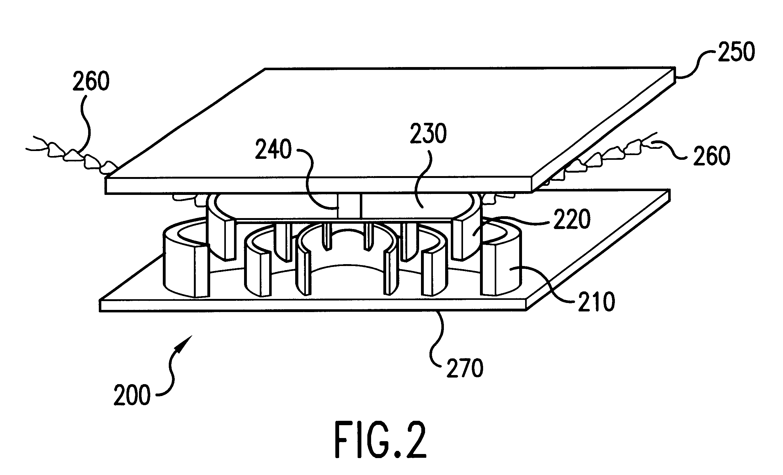
Therefore, in accordance with the present invention, a vertical comb mirror actuator (VCAM) having a set of interdigitized shells for actuating a deformable mirror is provided. The VCAM includes a set or array of stator shells and a corresponding set or array of movable slider shells. The mirror membrane is attached ...


PUM


Abstract

A deformable mirror includes a vertical comb actuator having a reflective surface attached thereto. The vertical comb drive includes stationary elements interspersed with moving elements. When a potential difference is provided between these elements, the moving elements are pulled downward, thereby deforming the reflective surface. The vertical comb drive typically includes a plurality of actuators, which are individually electrically addressed. Each actuator may be an array of interspersed elements or a cavity and corresponding tooth. Springs support the moving elements and bias the reflective surface in an original position. The vertical comb drive provides a large stroke and substantially linear voltage-versus-displacement curve throughout the stroke.

Description

1. Field of the InventionThe present invention relates to adaptive optics. More particularly, it relates to the use of a vertical comb drive to actuate the deformable mirror in an adaptive optical system.2. Description of Related ArtAtmospheric turbulence has frustrated astronomers ever since telescopes were invented. Atmospheric turbulence introduces aberrations on the wavefront of visible light, causing stars to twinkle and distant objects to shimmer. Atmospheric turbulence also limits the resolution of microscopes, endoscopes, and other optical imaging systems.Adaptive optics systems can be used to measure and compensate for rapidly fluctuating wavefront distortions which blur the images of objects viewed through the turbulent atmosphere. While many adaptive optics systems are currently being used, they suffer from many shortcomings. Current systems are typically complex, expensive, unreliable and difficult to maintain, thus putting them out of reach of amateur astronomers or com...

Claims


Application Information

Patent Timeline
Patent Type & Authority Patents(United States)
IPC IPC(8): G02B26/06G02B26/00G02B26/08G02B6/12
CPCG02B26/06G02B26/0841G02B2006/12104B81B3/0062B81B3/0086B81B2201/042B81B2203/0136B81B2203/053
Inventor CLARK, RODNEY L.HAMMER, JAY A.KARPINSKY, JOHN R.
Owner MEMS OPTICAL
Why Eureka
Try Eureka