Hollow optical waveguide for trace analysis in aqueous solutions
a technology of optical waveguides and trace analysis, applied in the field of detection, can solve the problems of difficult to distinguish between fluorescent light of interest, metal-coated capillaries have the disadvantage of high light loss, and the difficulty of on-line analysis using fluorescence measurements
- Summary
- Abstract
- Description
- Claims
- Application Information
AI Technical Summary
Benefits of technology
Problems solved by technology
Method used
Image
Examples
first embodiment
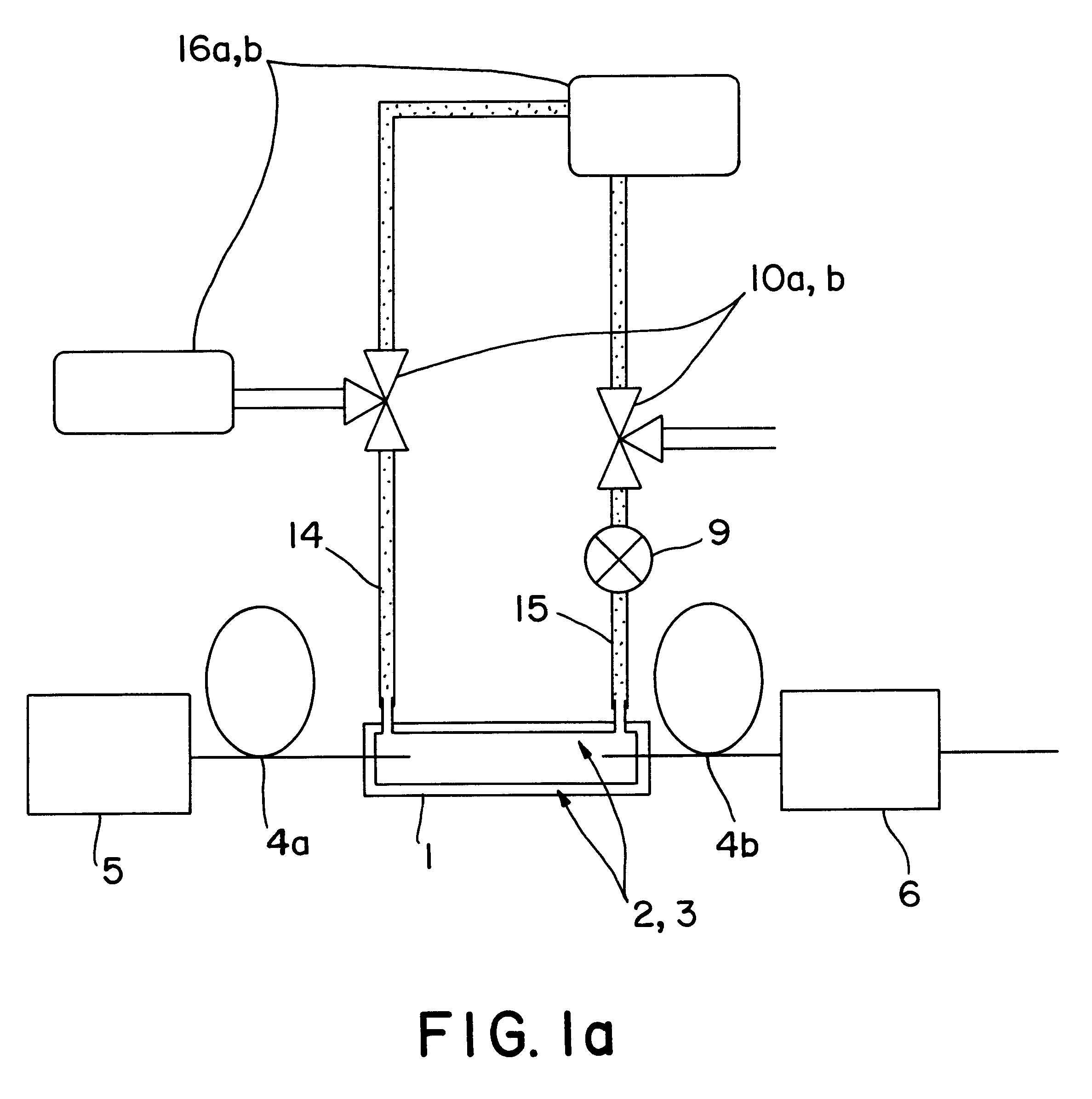
FIG. 1a schematically represents the use of the invention to detect an analyte by means of absorbance. The liquid core waveguide 1 comprises a cylindrical capillary 2 formed from glass or fused silica. The capillary 2 is provided with an inner coating 3 which, when the analyte is in an aqueous solution, is preferably comprised of Teflon AF. The source of analysis light 5, in an absorption application, preferably comprises a UV-light emitting deuterium lamp. Light source 5 is coupled to the waveguide core region, i.e., the analysis light is transmitted, via a fiber optic element 4a. In the FIG. 1a embodiment, the fiber optic element 4a consists of either a single fiber or bundle of fibers formed from hydrogen doped synthetic fused silica. Accordingly, analysis light having wavelengths as short as 180 nm may be utilized. Fiber optic element 4a passes through an end face of the capillary 2, i.e., extends into the liquid core of the waveguide, and is substantially coaxial with the capil...
second embodiment
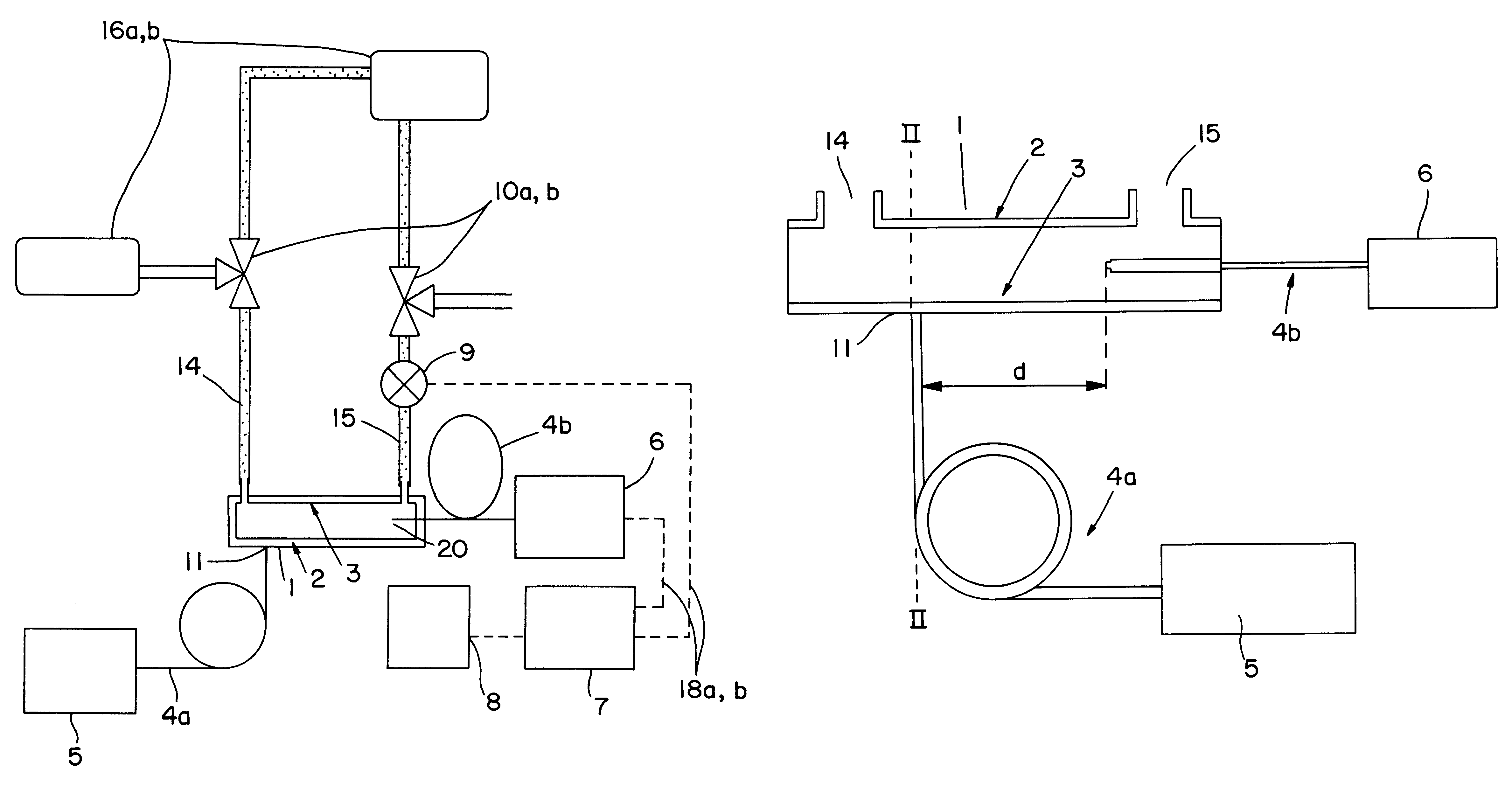
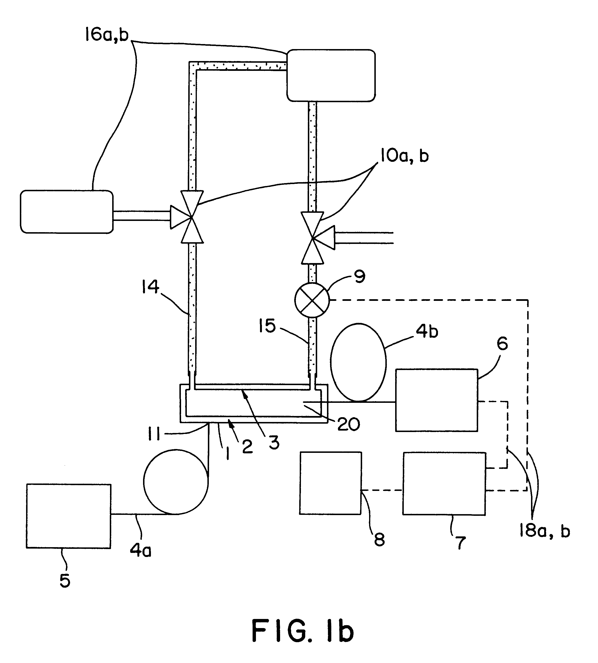
FIG. 1b depicts the use of apparatus in accordance with the present invention to detect dissolved materials in a solvent by means of measuring the fluorescence produced when such materials are excited by analysis light injected into the a, waveguide. In the FIG. 1b embodiment, the light from source 5 is coupled into the liquid core waveguide 1 from the side, i.e., the light is injected transversely with respect to a plain in which the axis of the waveguide lies. The coupling area 11, i.e., the interface between the end of the fiber optic element 4a and the exterior of the capillary 2 comprising waveguide 1, is displaced from the conduits 14 and 15 for the reason to be described below. Fluorescent light which is caused to be emitted by the excitation of dissolved material in the liquid core of the waveguide is collected in the region 20 and coupled out of the waveguide via fiber optic element 4b. The collected fluorescent light is delivered to detector 6 which provides an electrical ...
PUM
 Abstract
Description
Claims
Application Information
 - R&D
- Intellectual Property
- Life Sciences
- Materials
- Tech Scout
- Unparalleled Data Quality
- Higher Quality Content
- 60% Fewer Hallucinations
Browse by: Latest US Patents, China's latest patents, Technical Efficacy Thesaurus, Application Domain, Technology Topic, Popular Technical Reports.
© 2025 PatSnap. All rights reserved.Legal|Privacy policy|Modern Slavery Act Transparency Statement|Sitemap|About US| Contact US: help@patsnap.com


