Method of manufacturing thin plate magnet having microcrystalline structure

a technology of microcrystalline structure and thin plate magnet, which is applied in the direction of magnetic materials, nanomagnetism, magnetic bodies, etc., can solve the problems of narrow limit of the circumference speed range of the roller, limitations in the shape and utilization environment of the magnet, etc., and achieve the effect of smaller and thinner magnetic circuits

Inactive Publication Date: 2002-05-14
SUMITOMO SPECIAL METAL CO LTD
View PDF11 Cites 13 Cited by
  • Summary
  • Abstract
  • Description
  • Claims
  • Application Information

AI Technical Summary

Benefits of technology

An object of the present invention is to resolve the problems noted above in Nd--Fe--B magnets containing 6 at % or less of a rare earth element and exhibiting fine crystallization. Another object thereof is to obtain, by casting, magnets exhibiting a performance-to-cost ratio comparable to hard ferrite magnets and exhibiting an intrinsic coercive force iHc of 2.5 kOe or greater and a residual magnetic flux density Br of 9 kG or greater. Yet another object thereof is to provide a method for manufacturing thin-plate magnets having a fine crystalline structure and thickness of 70 to 500 .mu.m wherewith it is possible to make magnetic circuits smaller and thinner.

Problems solved by technology

There is a problem in this method of manufacturing Nd--Fe--B ternary magnets, however, in that the roller circumference speed range must be narrowly limited to obtain the hard magnetism.
As a consequence, not only is the thermal demagnetization great, but it is necessary also to raise the operating point of the magnets as high as possible, whereupon problems arise due to limitations in terms of magnet shape and utilization environment.

Method used


Image

  • Method of manufacturing thin plate magnet having microcrystalline structure
  • Method of manufacturing thin plate magnet having microcrystalline structure
  • Method of manufacturing thin plate magnet having microcrystalline structure

Examples


embodiment 1

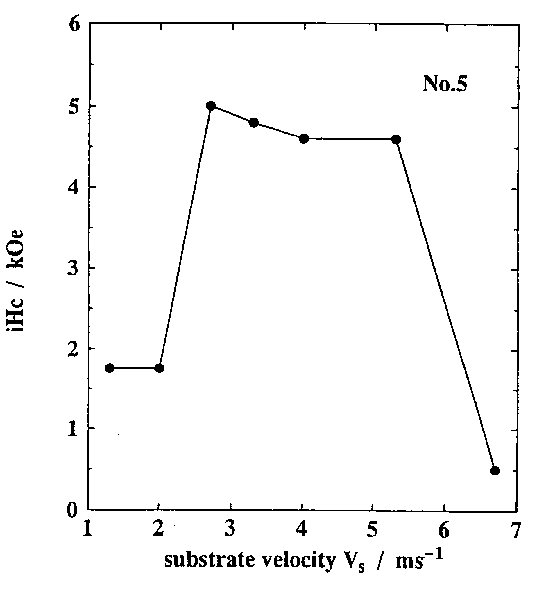
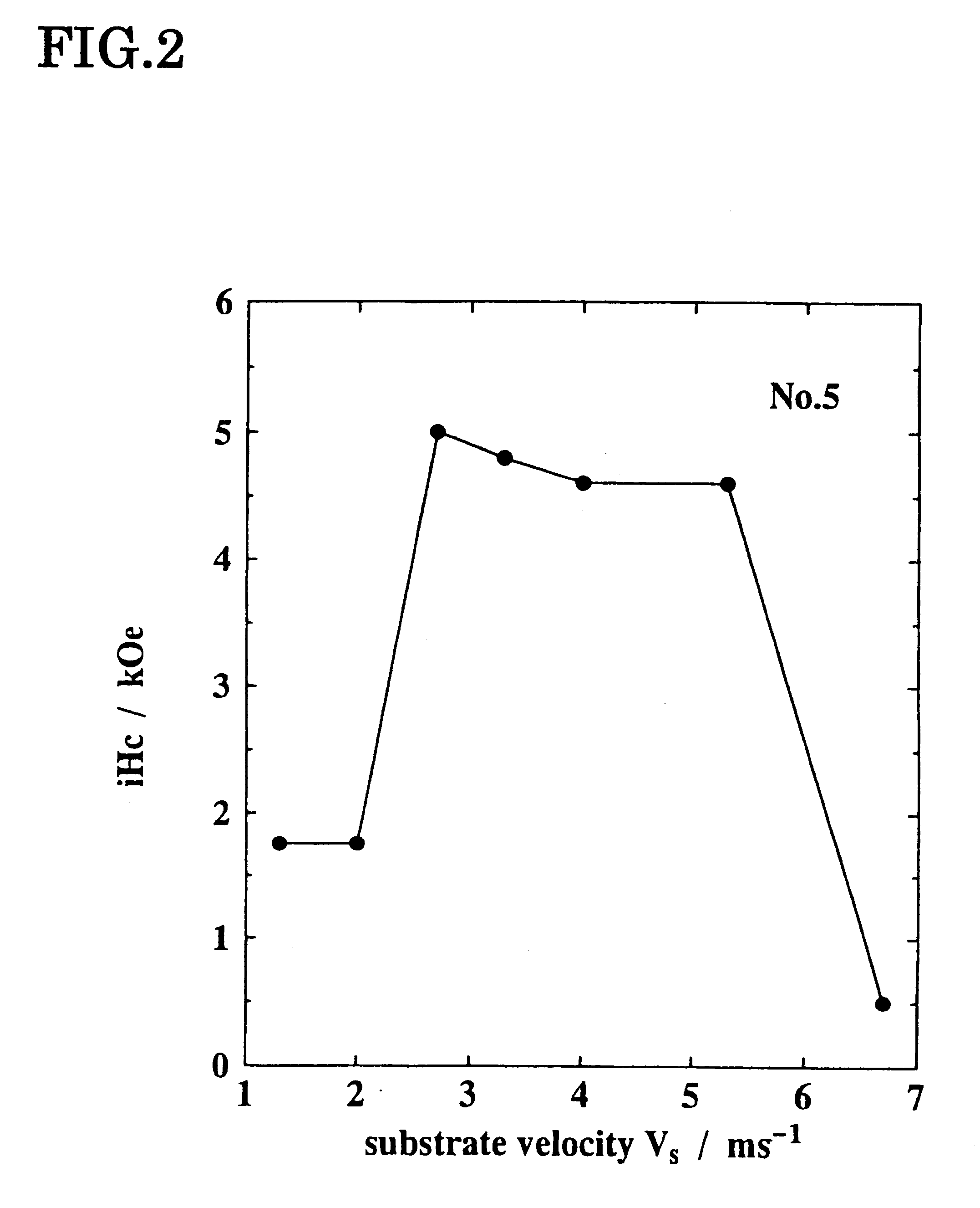
Pieces of the metals Fe, Co, C, Al, Si, Ti, V, Cr, Mn, Ni, Cu, Ga, Zr, Nb, Mo, Ag, Hf, Ta, W, Pt, Au, Pb, B, Nd, Pr, Dy, and Tb, at a purity of 99.5% or greater, were measured to obtain a total weight of 30 g. The raw material was placed in a quartz crucible having in the bottom thereof a slit measuring 0.3 mm.times.8 mm, and melted by induction heating in an Ar atmosphere maintained at the rapid solidification atmosphere pressure noted in Table 1. After bringing the melting temperature to 1300.degree. C., the molten surface was pressurized with Ar gas and, at room temperature, the melt was continuously cast from a height of 0.7 mm at the outer circumferential surface of a Cu cooling roller turning at the roller circumferential speed indicated in Table 1-2. Thus was fabricated continuous thin-plate rapidly solidified alloy at a width of 8 mm.

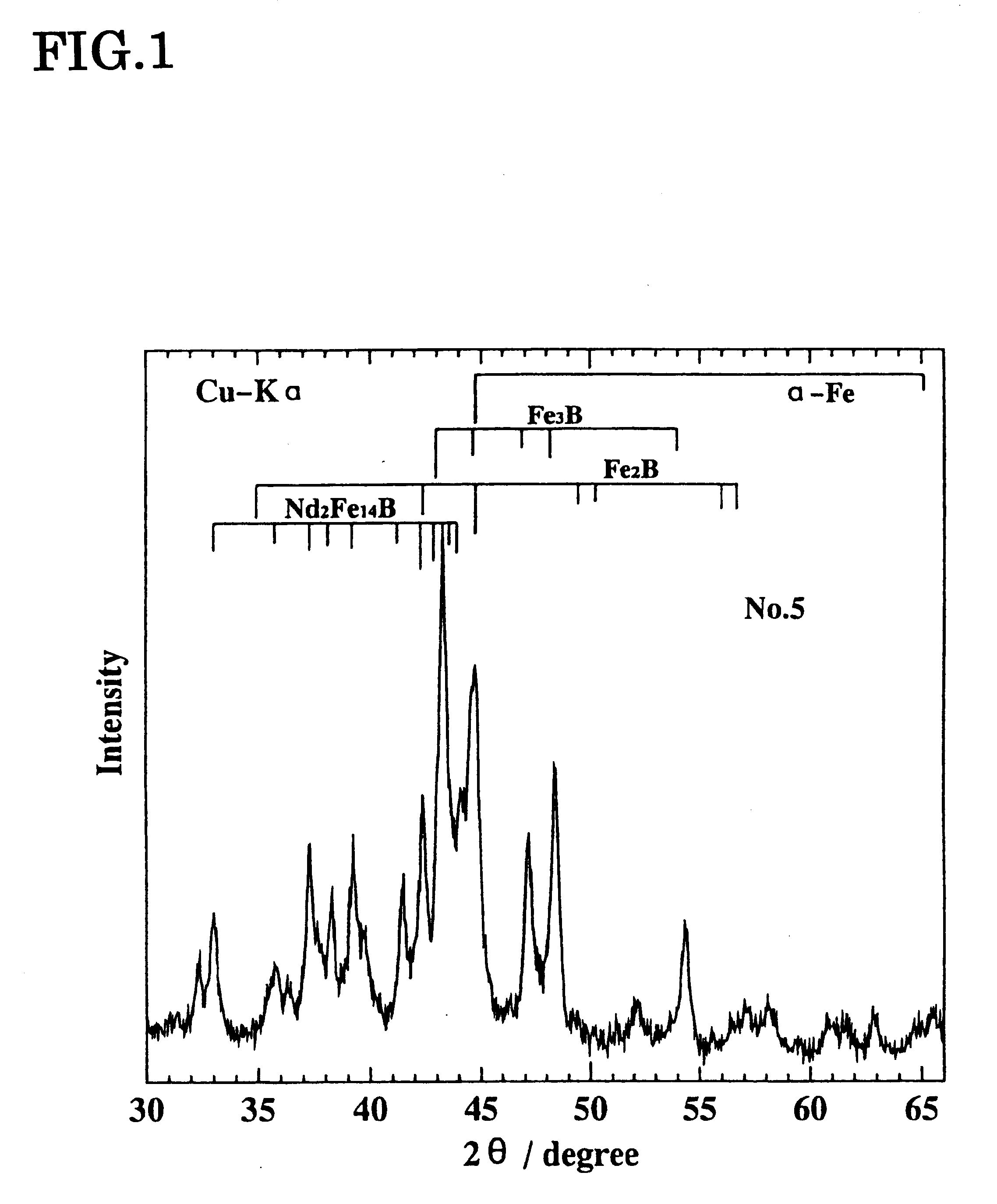
As indicated by the Cu--K.alpha. characteristic x-ray induced x-ray diffraction pattern for Embodiment Example No. 5 given in FIG. 1, it is ver...

embodiment 2

In No. 1, No. 3, and No. 17 in Table 1-1, the mean crystalline grain diameter was less than 10 nm, wherefore the rapid solidified alloys were heat-treated by maintaining them at 670.degree. C. for 10 minutes in Ar gas to make the mean crystalline grain diameter 10 nm or greater. The magnetic properties were determined as in the first embodiment by measurements made using a VSM on the thin-plate magnets fabricated into prescribed shapes. The measurement results are given in Table 2.


PUM

PropertyMeasurementUnit
mean crystalline grain diameteraaaaaaaaaa
thicknessaaaaaaaaaa
grain diameteraaaaaaaaaa

Abstract

The present invention is presented with the object of providing a manufacturing method for thin-plate magnets that, as cast, exhibit an intrinsic coercive force iHc of 2.5 kOe or greater and a residual magnetic flux density Br of 9 kG or greater, exhibit a performance-to-cost ratio comparable to hard ferrite magnets, and exhibit a fine crystalline structure with a thickness of 70 to 500 mum wherewith magnetic circuits can be made smaller and thinner. By employing alloy melts to which specific elements have been added, in a process wherein alloy melts of specific composition are continuously cast on a rotating cooling roller or rollers in a reduced-pressure inert or inactive gas atmosphere at 30 kPa or less, and fine crystalline permanent magnets having a fine crystalline structure of 10 to 50 nm are fabricated, fine crystalline permanent magnets having a thickness of 70 to 500 mum can be obtained wherein iHc is improved to 2.5 kOe or greater, and the ideal roller circumferencied speed range wherein hard magnetic properties are manifested can be broadened as compared to the conditions under which Nd-Fe-B ternary magnets are fabricated.

Description

This invention relates to a manufacturing method for thin-plate magnets ideal for magnetic circuits used in various small motors, actuators, and magnetic sensors, etc. In the present invention, magnets are obtained, by the method of continuously casting a melt having a specific composition containing 6 at % or less of a rare earth element and 15 to 30 at % boron, on a turning cooling roller or rollers, in a prescribed reduced-pressure inactive gas atmosphere, so that the magnets have a crystalline structure wherein, in the state wherein they are cast, 90% or more is actually constituted by an Fe.sub.3 B compound and .alpha.-Fe coexisting with a compound phase having an Nd.sub.2 Fe.sub.14 B crystalline structure, and exhibit a fine crystalline structure having for each configuring phase a mean crystal grain diameter of from 10 to 50 nm. The present invention relates to a method of manufacturing thin-plate magnets, immediately from the alloy melt, having a fine crystalline structure w...

Claims


Application Information

Patent Timeline
Patent Type & Authority Patents(United States)
IPC IPC(8): C22C38/00H01F1/057H01F1/032H01F1/058
CPCB82Y25/00H01F1/058H01F1/0579C22C38/002H01F1/057
Inventor KANEKIYO, HIROKAZUHIROSAWA, SATOSHI
Owner SUMITOMO SPECIAL METAL CO LTD
Why Eureka
Try Eureka