
Method and control apparatus for tracking a contrast agent in an examination subject using a medical imaging device

Inactive Publication Date: 2002-05-28
SIEMENS AG
View PDF10 Cites 64 Cited by
  • Summary
  • Abstract
  • Description
  • Claims
  • Application Information

AI Technical Summary

Benefits of technology

It is an object of the present invention to provide a method of the type described above wherein a low volume of contrast agent suffices and wherein image data acquisition can be chronologically synchronized, with optimal precision, with the arrival of a contrast agent bolus in the relevant examination region.
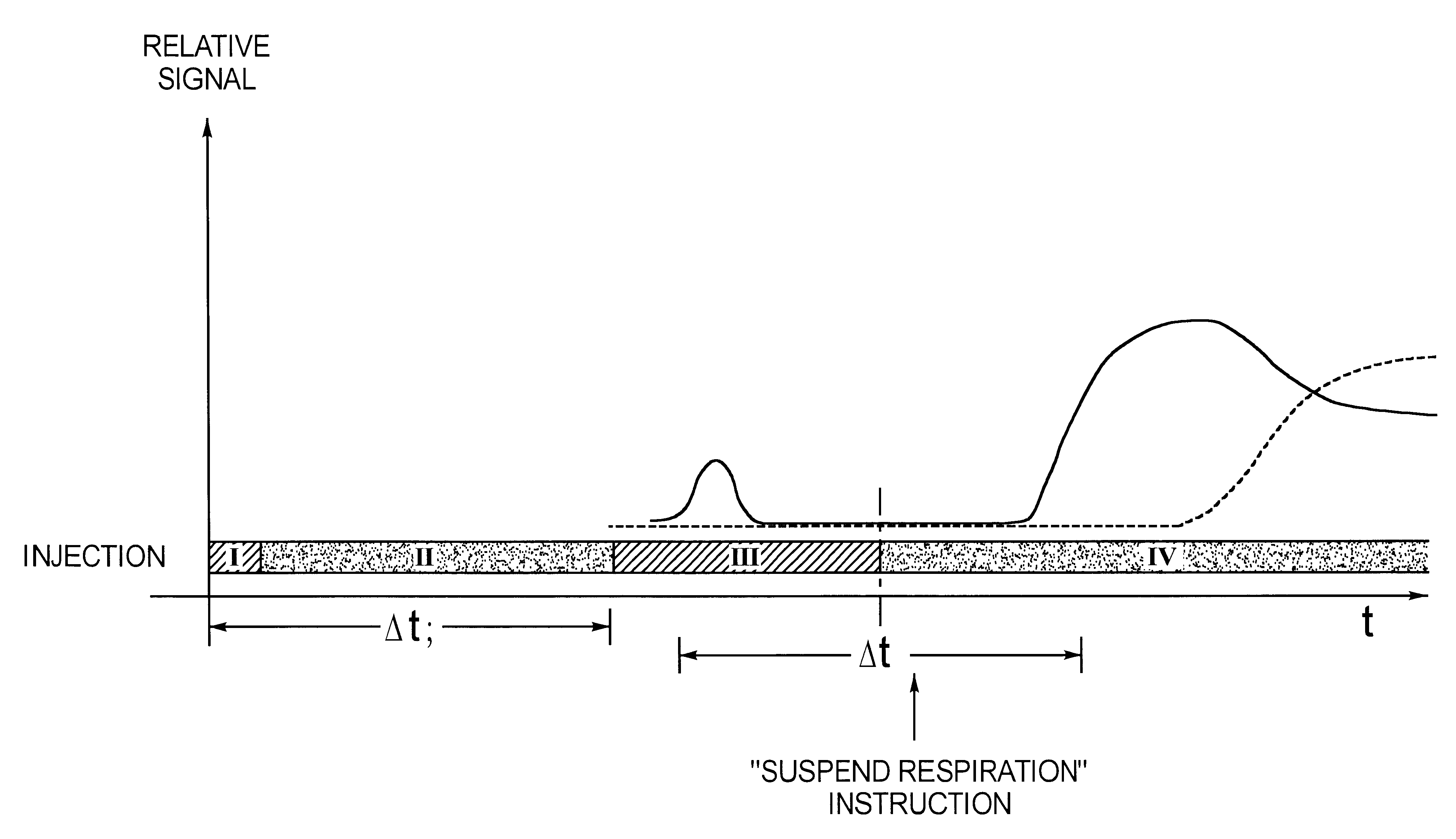
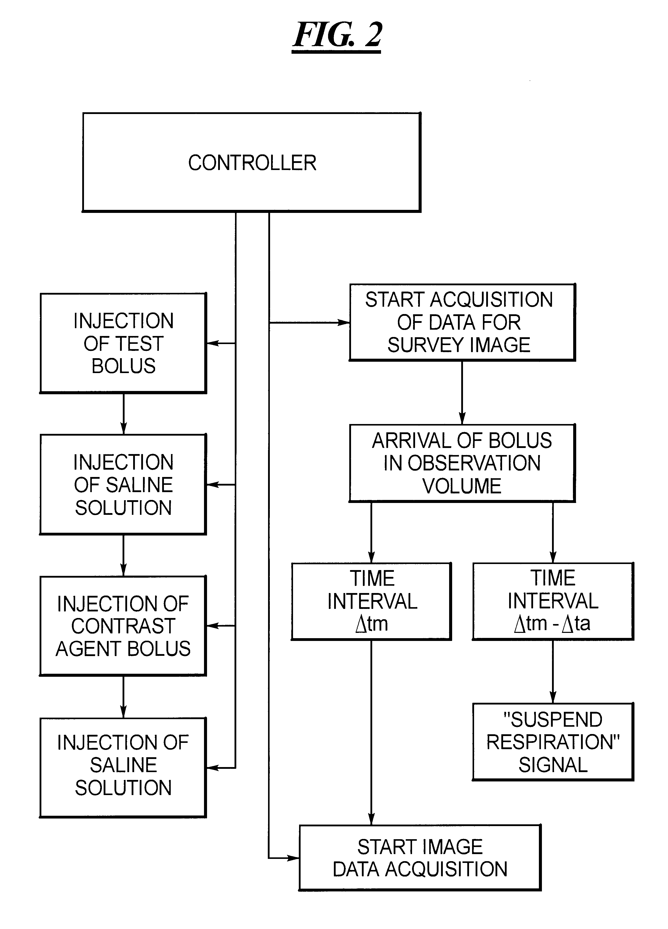
By means of the two-stage injection of the contrast agent at a precisely defined interval, a precise time for the optimal start of the image data acquisition, and also for the instruction, if needed, to suspend respiration, is obtained. Since the available measuring time can be used optimally, a small volume of contrast agent suffices. In an embodiment of the method, image data acquisition is automatically started at the predetermined time interval subsequent to the arrival of the test bolus. While the known methods require a considerable degree of attention from the examining doctor, particularly if an instruction to suspend breathing is necessary, the inventive method can be conducted entirely automatically. This reduces the error rate considerably. With a control apparatus and two infusion pumps, the contrast agent injection can also be automated.

Problems solved by technology

This method only requires an injection with a normal dose, however, with this method a time problem results in MR angiography, particularly if the image data measurement must be performed in an arrested-breathing phase.
The remaining measuring time may already be too short for MR angiography.
One solution would be to increase the contrast agent volume, in order to extend the available measuring time, however, due to possible side effects and also due to cost, it is desirable to keep the contrast agent volume small.

Method used


Image

  • Method and control apparatus for tracking a contrast agent in an examination subject using a medical imaging device
  • Method and control apparatus for tracking a contrast agent in an examination subject using a medical imaging device
  • Method and control apparatus for tracking a contrast agent in an examination subject using a medical imaging device

Examples


Embodiment Construction

The inventive method is described below in the context of a nuclear spin tomography examination (also referred to as MR, for magnetic resonance) which is supported by a contrast agent. The method, however, can also be analogously applied to other imaging modalities, such as computed tomography; it is usually necessary to use larger contrast agent volumes in computed tomography.

According to FIG. 1, a test bolus of about 1 ml is injected in a time period 1, which is illustrated in hatched fashion. For MR measurements, a paramagnetic contrast agent is required, such as is commercially available from Schering under the name Magnevist.RTM.. The injection of the test bolus is followed by the injection of a saline solution (characterized by a dotted surface) in a phase II and this is in turn followed by another contrast agent injection at a full dose in a phase III, i.e. the main bolus. The duration of the injection of saline solution in phase II determines the interval between the test bo...


PUM


Abstract

In a method and control apparatus for tracking a contrast agent using an imaging medical device a test bolus of a contrast agent is initially injected into an examination subject, followed by an injection of a main bolus at a time interval of .DELTA.ti. The arrival of the test bolus in the observation volume is chronologically determined by periodically repeated survey measurements. An image data measurement is started at a time interval .DELTA.tm subsequent to the detection of the test bolus, this time interval .DELTA.tm being defined according to the prescribed time interval .DELTA.ti.

Description

BACKGROUND OF THE INVENTION1. Field of the InventionThe present invention is directed to a method as well as to a control apparatus for tracking a contrast agent in an examination subject using a medical imaging device, such as a magnetic resonance imaging apparatus or a computed tomography apparatus, in which the examination subject is disposed.2. Description of the Prior ArtIn examinations involving a contrast agent, it is often required to trigger pickup at that time at which a previously injected volume of contrast agent reaches the examination volume of interest. The contrast agent is typically injected intravenously, and the examination is conducted as soon as the contrast agent is located in certain arteries. For example, in dynamic liver examinations, the liver is recorded during the arterial phase. There are different approaches with respect to this timing, according to the imaging method applied. In the increasingly popular MR angiography involving a contrast agent, care m...

Claims


Application Information

Patent Timeline
IPC IPC(8): A61B5/055G01R33/28A61B6/00
CPCA61B5/055G01R33/5601A61B6/504A61B6/481
Inventor REQUARDT, MARTIN
Owner SIEMENS AG
Learn More