Compact all-weather electromagnetic imaging system

an electromagnetic imaging system and compact technology, applied in the field of imaging systems, can solve the problems of large volume, high cost of super heterodyne receivers and accompanying microelectronic circuits, and undesirable systems

Inactive Publication Date: 2002-06-11
RAYTHEON CO
View PDF3 Cites 27 Cited by
  • Summary
  • Abstract
  • Description
  • Claims
  • Application Information

AI Technical Summary

Problems solved by technology

Unfortunately, in warfare applications, an enemy may detect the transmitted electromagnetic energy, making the systems undesirable in many applications.
Clouds, rain, or snow may block optical and infrared electromagnetic energy.
The super heterodyne receivers and accompanying microelectronic circuits are expensive, bulky, consume excess power, and typically offer relatively poor resolution.
Electromagnetic diffraction creates detector size versus wavelength design limitations that may further increase system size, especially in systems employing full 256.times.256 detector FPAs.
In many applications, the present state of the art results in very large systems.
Space-constraints necessitate the use of a partial FPA and an accompanying mechanical scanning mechanism.
The mechanical scanning mechanisms may further increase system size and cost while reducing system reliability and performance.
To achieve effective SNRs, the systems may require undesirably long image integration times. Therefore, systems employing mechanical FPA scanners typically cannot operate in real-time and have compromised SNRs.
Consequently, conventional millimeter wave imaging systems are impractical in many applications.

Method used


Image

  • Compact all-weather electromagnetic imaging system
  • Compact all-weather electromagnetic imaging system
  • Compact all-weather electromagnetic imaging system

Examples


Embodiment Construction

While the present invention is described herein with reference to illustrative embodiments for particular applications, it should he understood that the invention is not limited thereto. Those having ordinary skill in the art and access to the teachings provided herein will recognize additional modifications, applications, and embodiments within the scope thereof and additional fields in which the present invention would be of significant utility.

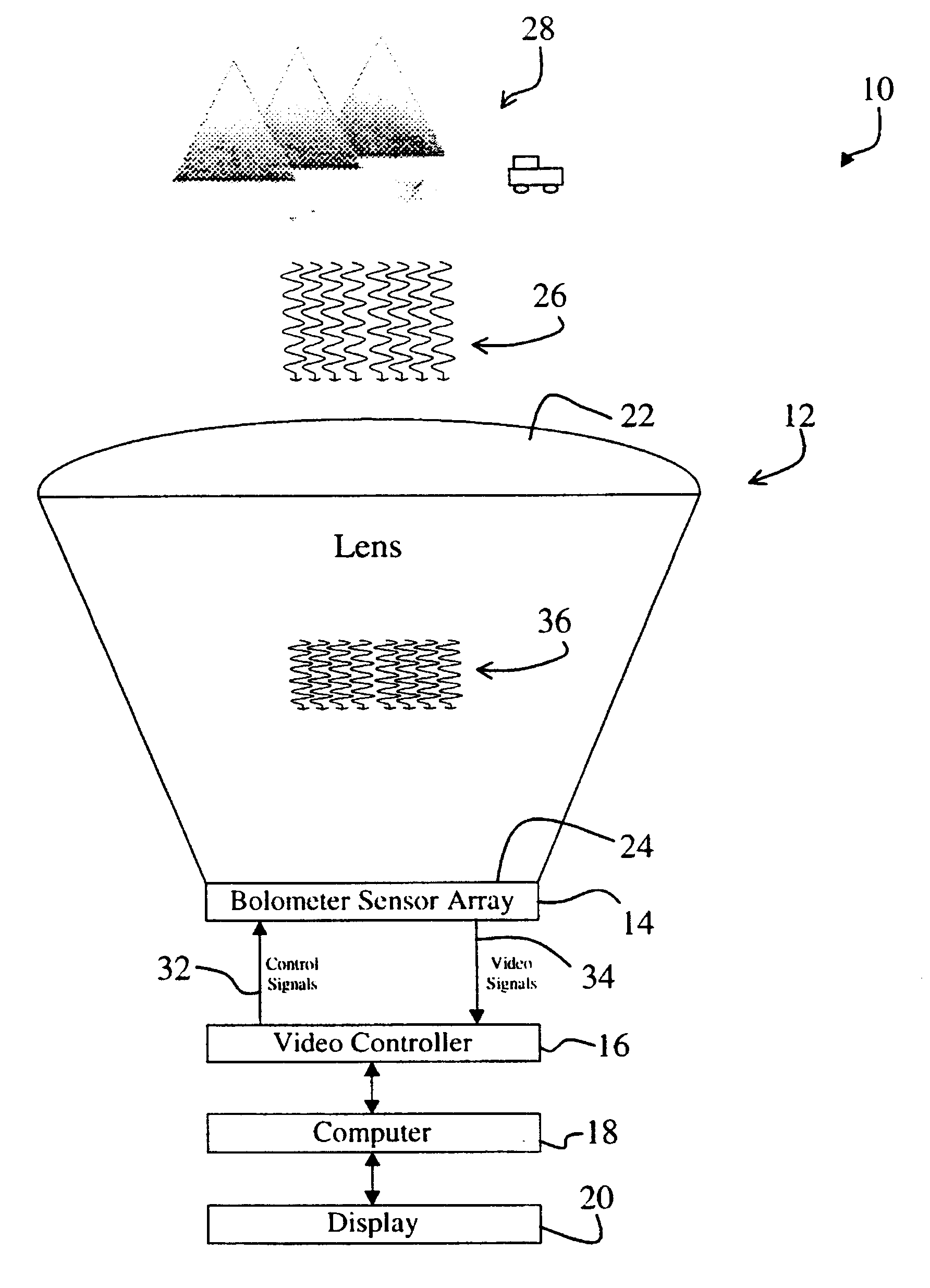
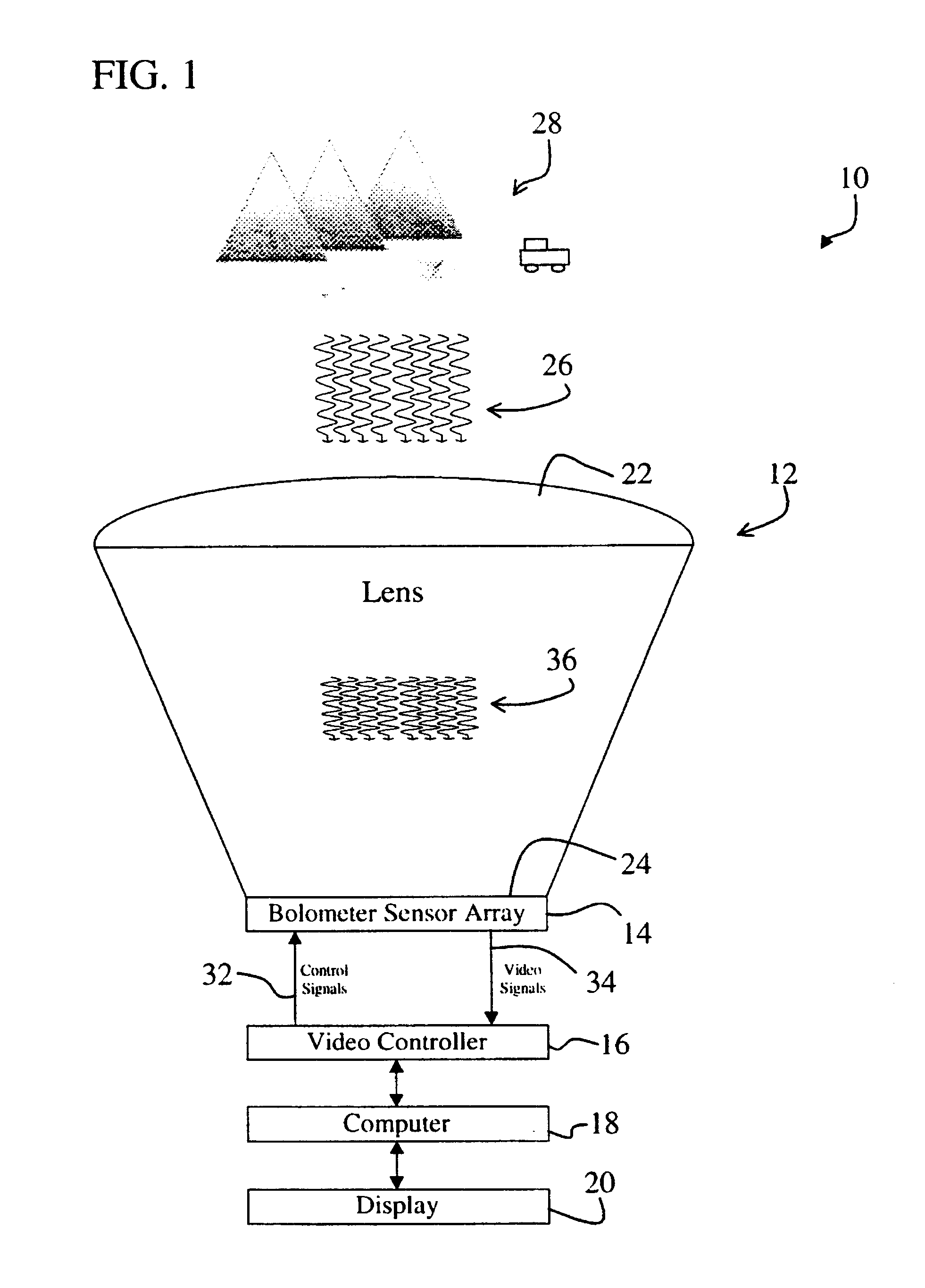
FIG. 1 is a diagram of an imaging system 10 constructed in accordance with the teachings of the present invention showing a special lens 12, a bolometer sensor array circuit 14, a video controller 16, a computer 18, and a display 20. The lens 12 includes an input aperture 22 and an output aperture 24. The bolometer sensor array circuit 14 is mounted to the output aperture 24 of the lens 12. The bolometer sensor array circuit 14 is connected to the video controller 16, which is connected to the computer 18, which is connected to the display ...


PUM


Abstract

The system (10) includes a first mechanism (12) for receiving electromagnetic energy of a first wavelength from the scene (28) and providing electromagnetic energy of a second wavelength shorter than the first wavelength. A second mechanism (14) measures variations of the electromagnetic energy of the second wavelength over a predetermined area. The system is a millimeter wave imaging system (10). The first mechanism (12) includes a lens (12) having an index of refraction substantially greater than 1. The lens (12) is opaque to infrared electromagnetic energy and made of alumina, plastic, or other material having a relatively high index of refraction. The second mechanism (24) includes and array of bolometers (24) positioned parallel to an output aperture (24) of the lens and within a distance of the output aperture (24) that is much smaller than the second wavelength. A video controller (16), a computer (18), process video signals output from the array of bolometers (14) to yield an image, which is displayed on a display (20).

Description

1. Field of InventionThis invention relates to imaging systems. Specifically, the present invention relates to millimeter wave electromagnetic imaging systems.2. Description of the Related ArtElectromagnetic imaging systems are employed in a variety of demanding applications including security surveillance, aircraft landing, missile guidance, target detection and classification, terrain mapping, and mine detection applications. Such applications require cost-effective, space-efficient, and reliable imaging systems that can provide effective images at night and in adverse weather conditions.Imaging systems are either passive or active. Both passive and active electromagnetic imaging systems are typically named in accordance with the frequency band of electromagnetic energy employed by the systems.Active electromagnetic imaging systems, such as radar systems, transmit electromagnetic energy toward a scene and detect the reflected electromagnetic energy to generate an image of the scen...

Claims


Application Information

Patent Timeline
Patent Type & Authority Patents(United States)
IPC IPC(8): G01V8/00H01Q19/06H01Q19/00
CPCH01Q19/06G01V8/005
Inventor GRINBERG, JANHARVEY, ROBINDOLEZAL, FRANKLIN A.
Owner RAYTHEON CO
Why Eureka
Try Eureka