Optical fiber and optical transmission line using the same

a technology of optical fiber and optical transmission line, applied in the direction of cladded optical fibre, instruments, optical elements, etc., can solve the problems of loss of reliability of optical transmission, deterioration of optical transmission quality, and trouble in long-distance optical transmission, so as to reduce the loss of macrobend in the wavelength band of 1.55 .mu.m., the effect of increasing the effective core sectional area and positive dispersion slop

Inactive Publication Date: 2002-06-11
FURUKAWA ELECTRIC CO LTD
View PDF14 Cites 24 Cited by
  • Summary
  • Abstract
  • Description
  • Claims
  • Application Information

AI Technical Summary

Benefits of technology

Therefore, a method was established in that, at the outer circumference of the side core in the W-formed refractive index profile, a segment core having a refractive index higher than that of the side core was provided, and light which leaked from the center core of the W-formed refractive index profile and could not be transmitted was confined (not allowed to escape to the cladding side) by the segment core with a high refractive index, whereby the light was transmitted and the abovementioned macrobend loss was reduced. In addition, it was proved that, by this method, light was transmitted while spreading toward portions other than the center portion of the center core, whereby the effective core sectional area substantially became larger, and the power density of the light to be transmitted was reduced.
Furthermore, since the refractive index profile of the present embodiment has a construction in that a core layer with a refractive index higher than that of side core layer 12 is provided at the outer circumference of the side core layer 12 whose refractive index is low in the W-formed refractive index profile shown in FIG. 7, the core layer (second side core 3) outside the core layer (first side core 2) with the low refractive index confines light that is in a condition where it has leaked from the center core of the W-formed refractive index profile and cannot be transmitted (that is, prevents light leakage toward the cladding side), whereby the light is transmitted while widely spreading to the portion other than the center of the center core 1, and therefore, the effective core sectional area is substantially increased to reduce the power density of the light to be transmitted. In the present embodiment, if the absolute value of .DELTA.3 is set to be larger than that of .DELTA.2, that is, if .vertline..DELTA.3.parallel.>.vertline..DELTA.2.parallel., other properties when the absolute value of the negative dispersion and the absolute value of the negative dispersion slope are made large are improved. This is preferable.

Problems solved by technology

Therefore, in the case where optical transmissions are carried out by using a wavelength band near 1.3 .mu.m, the optical amplifier cannot be used, and therefore, trouble may occur in long-distance optical transmissions.
Therefore, distortion in waveform of the light signals of the respective multiplexed wavelengths increases as the light signals are transmitted in the single-mode optical fiber, separation and distinction of the signals at the receiver side become difficult, the quality of optical transmissions deteriorates, and the reliability of optical transmissions is lost.
However, if a dispersion shifted optical fiber having the abovementioned minute dispersion is used for long-distance optical transmissions, since the influence of the minute dispersion cannot be ignored, it is difficult to dependently use the dispersion shifted optical fiber having minute dispersion for long-distance large-capacity and high-rate transmissions.
However, the dispersion value of the optical fiber having a refractive index profile of a single-peak form in the wavelength band of 1.55 .mu.m is approximately -80 ps / nm / km at most as a limit value in practical use, and therefore, an optical fiber having a smaller dispersion value (absolute value of negative dispersion is great) cannot be realized by means of a refractive index profile of a single-peak form.
Therefore, in order to compensate for the positive dispersion of the single-mode optical fiber by an optical fiber with a refractive index profile of a single-peak form, the length required for the optical fiber for dispersion compensation increases, so that it is difficult to reduce the size of an optical fiber for dispersion compensation in which the abovementioned optical fiber is coiled and housed.
Furthermore, in the optical fiber with a refractive index profile of a single-peak form, the dispersion slope in the wavelength band of 1.55 .mu.m is positive, so that it is difficult to compensate for the chromatic dispersion of the single mode optical fiber over a broadband of a 1.55 .mu.m wavelength band.
However, the optical fiber having the W-formed refractive index profile is difficult to form so that a negative dispersion slope is provided which can completely compensate for the positive dispersion slope of an optical fiber to be compensated at the wavelength of 1.55 .mu.m being the central wavelength of the wavelength band of 1.55 .mu.m, and dispersion is less than -120 ps / nm / km.
Therefore, also in the case of using the optical fiber having the W-formed profile, the length of optical fiber required for compensation of dispersion of the single-mode optical fiber increases, so that it is difficult to reduce the size of an optical fiber module which is formed by coiling and housing said optical fiber in a case.
Furthermore, in both cases of the single-peak form and W-form of the prior-art optical fibers, the range of light transmission (effective core sectional area) in the single-mode is small, the power density of the light transmitted inside the optical fiber is high, and in addition, as mentioned above, the length of the optical fiber used is long, so that the non-linear phenomenon is easily generated inside the optical fiber.
If so, distortion in signal waveform occurs due to this non-linear phenomenon, whereby transmissions cannot be correctly carried out, and therefore, the use of the dispersion compensating device using the optical fibers is inevitably limited.
Moreover, it also can be considered that deterioration of transmission signals due to chromatic dispersion is prevented by using the optical fiber for compensating dispersion of a dispersion shifted optical fiber having minute dispersion, however, it is considered difficult to completely compensate for the dispersion and dispersion slope of a dispersion shifted optical fiber having minute dispersion by the optical fiber having a single-peak or W-formed refractive index profile.

Method used


Image

  • Optical fiber and optical transmission line using the same
  • Optical fiber and optical transmission line using the same
  • Optical fiber and optical transmission line using the same

Examples


first embodiment

As for the optical fibers shown in Table 4, although concrete refractive index profiles are not shown, all the profiles are determined so that the effective cut-off wavelength becomes less than 1550 nm within the range of the refractive index profile determined in the

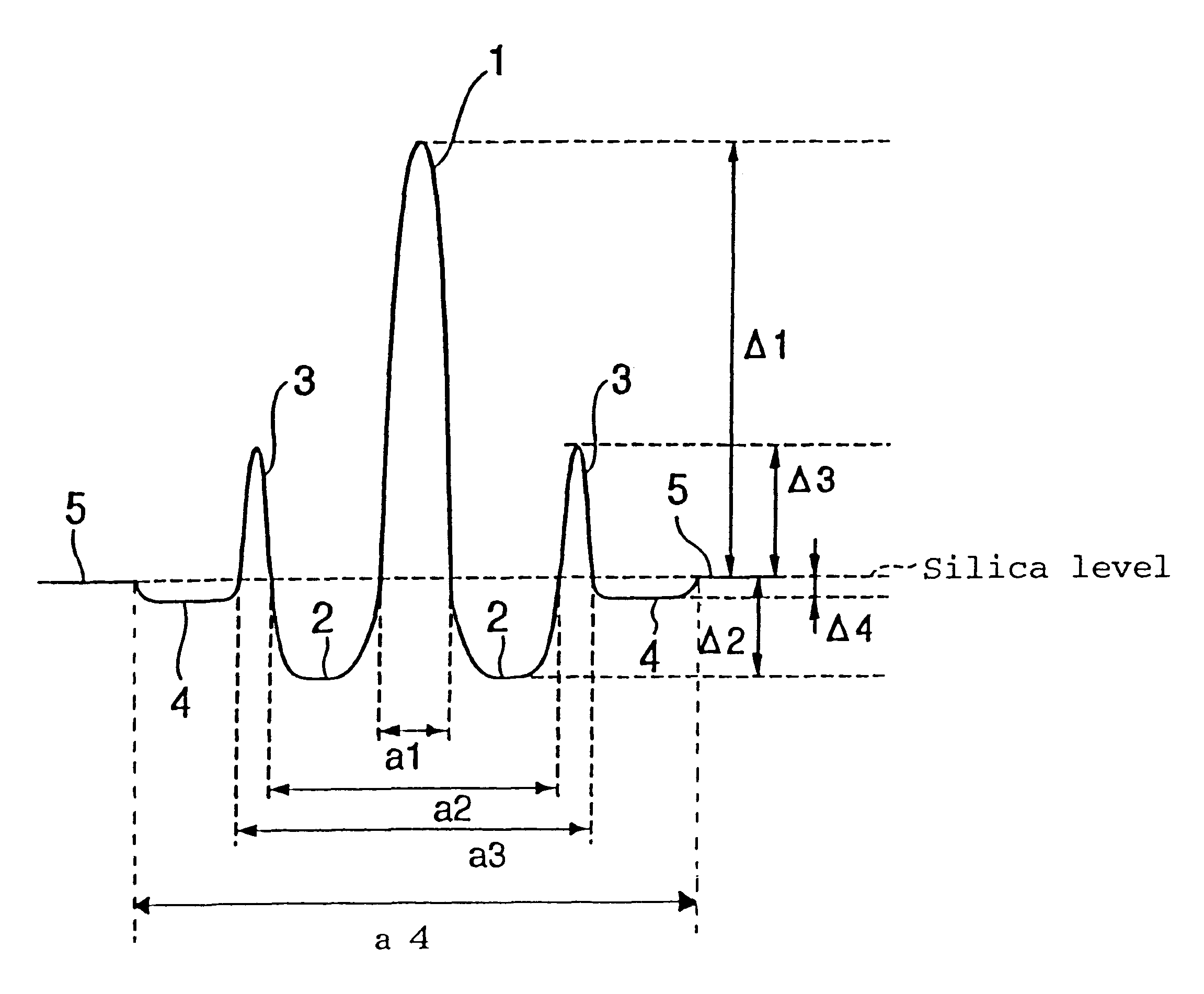
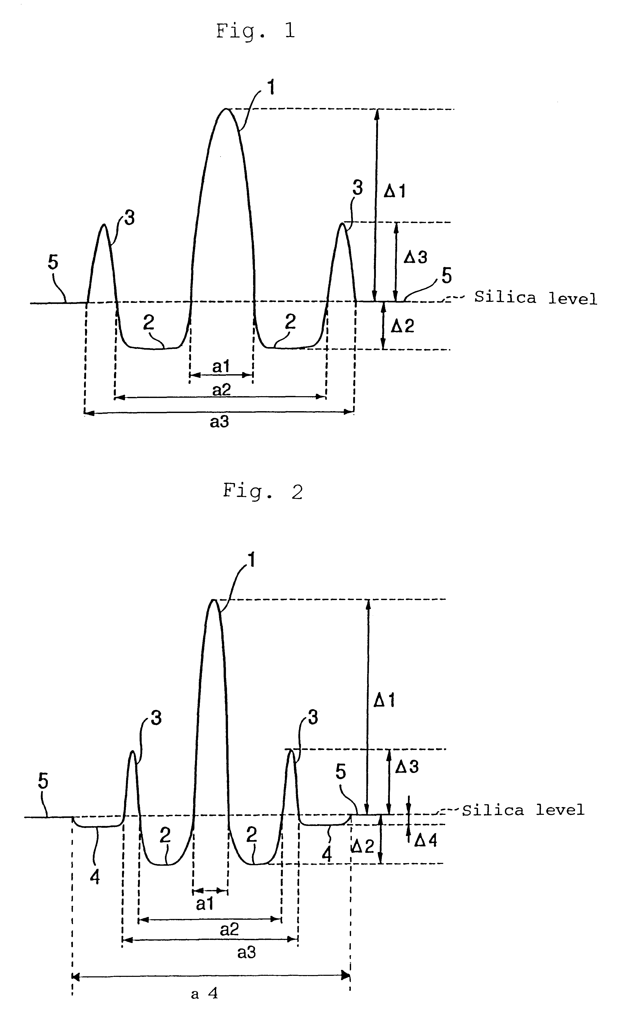
The present inventor found that, by setting the relative index differences .DELTA.1, .DELTA.2, and .DELTA.3 and the parameters of the diameter a1 of the center core 1, diameter a2 of the first side core 2, and diameter a3 of the second side core 3 to be within the range specified in the first embodiment, the absolute value of negative dispersion and absolute value of the negative dispersion slope per unit length in the wavelength band in use of, for example, 1.55 .mu.m were set to be large, and it becomes possible to compensate for the positive dispersion of the single-mode optical fiber over a broadband of the wavelength band in use, the effective cut-off wavelength might be at the side of a wavelength longer than the ...

second embodiment

The second embodiment is thus arranged, and is characterized in that, by providing the inner cladding 4 with a low refractive index at the outer circumferential side of the second side core 3, light of an LP.sub.11 mode having electric field distribution in a wide range in the direction of the core diameter is made to easily leak to shorten the effective cut-off wavelength.

in the case where the second side core 3 with a high refractive index is provided at the circumference of the first side core 2 as in the invention, high negative dispersion and high negative slope are realized, however, depending on the refractive index profile of the optical fiber, the effective cut-off wavelength may become longer. If so, the optical fiber cannot carry out single-mode operation, so that, in order to securely prevent the effective cut-off wavelength from lengthening, the inner cladding 4 with a low refractive index is provided at the outer circumferential side of the second side core 3 as mentio...

concrete example

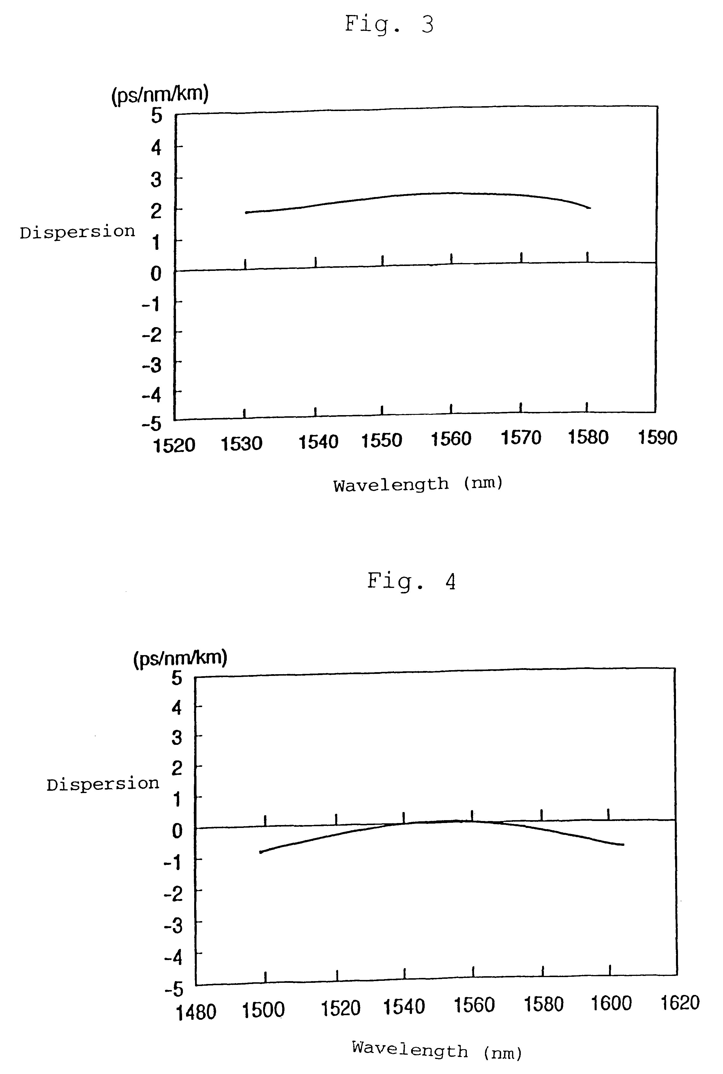
In Table 5, as a concrete example of the second embodiment, the construction and properties of an optical fiber of concrete example 11 are shown together with concrete example 10 of the optical fiber of the abovementioned first embodiment. In addition, the relative index differences .DELTA.1 through .DELTA.3 are determined by the abovementioned formulas (1) through (3). The values of chromatic dispersion, dispersion slope, D / S, and Aeff are determined in the same manner as in Tables 1 and 2.

As is clearly understood from this Table 5, by providing the inner cladding 4, the effective cut-off wavelength can be made shorter, and furthermore, the Aeff can be made larger. In addition, in the case where the inner cladding 4 with a low refractive index is provided at the outer circumferential side of the second side core 3, it is not always necessary that the maximum refractive index point 3a of the second side core 3 be set at the side of the first side core 2 from the center C of the widt...


PUM


Abstract

The present invention provides an optical fiber which has negative dispersion and negative dispersion slope in a wavelength band in use, and can carry out single-mode operation in which distortion due to the non-linear phenomenon can be suppressed so as to be suitable for wavelength multiplexed optical transmissions. When the relative index differences of center core (1), first side core (2), second side core (3), and inner cladding (4) from the silica level are DELTA1, DELTA2, DELTA3, and DELTA4, l.7%<=DELTA1, DELTA2<=-0.3%, 0.25%<=DELTA3, and DELTA4<0. Furthermore, the value A, determined by dividing the diameter a1 of the center core 1 by the diameter a2 of the first side core 2, is set to 0.15<=A<=0.2, and the value B, determined by dividing the diameter a3 of the second side core 2 by the diameter a2 of the first side core 3, is set to 1<B<=2. By such an arrangement, the absolute values of the negative dispersion and negative dispersion slope in a wavelength band of 1.55 mum can be made large, and in addition, light is confined within the core by the second side core (3), the effective core sectional area is made larger, and inner cladding (4) is provided, whereby the effective cut-off wavelength is shortened.

Description

The present invention relates to an optical fiber which is suitable for wavelength multiplexed optical transmissions in, for example, a wavelength band of a 1.55 .mu.m wavelength and a wavelength multiplexed optical transmission line using the same optical fiber.As a transmission network for optical transmissions, a single-mode optical fiber having zero dispersion in a wavelength band of a 1.3 .mu.m wavelength has been laid across the world. Recently, in accordance with development of the information society, information transmission capacities tend to significantly increase. In accordance with such an increase in information, wavelength multiplexed transmissions (WDM transmissions) are widely accepted in the transmission field, and now the age of wavelength multiplexed transmissions has been entered. Wavelength multiplexed transmissions are the method for transmitting a plurality of light signals which are not on one wavelength but are divided into a plurality of wavelengths, which...

Claims


Application Information

Patent Timeline
Patent Type & Authority Patents(United States)
IPC IPC(8): G02B6/02G02B6/036
CPCG02B6/02019G02B6/03666G02B6/03644G02B6/02261
Inventor ARAI, SHINICHISUGIZAKI, RYUICHIAISO, KEIICHI
Owner FURUKAWA ELECTRIC CO LTD
Why Eureka
Try Eureka