Method and apparatus for enhancing power output and efficiency of combustion turbines

Inactive Publication Date: 2002-06-25
CHICAGO BRIDGE & IRON CO
View PDF3 Cites 25 Cited by
  • Summary
  • Abstract
  • Description
  • Claims
  • Application Information

AI Technical Summary

Benefits of technology

Accordingly, it is an object of the present invention to provide a method and an apparatus for improving and enhancing the po

Problems solved by technology

The available power output of internal combustion engines, however, typically diminishes with rising inlet air temperature.
Although quite low in unit capital cost, that is, capital cost per unit of incremental power output, evaporative cooling can only cool the air to a temperature near the ambient wet bulb temperature.
Therefore, this method has quite limited value in terms of power output enhancement, especially on hot, humid days when it is most needed.
Absorption cooling is able to be powered by heat recovered from the combustion turbine exhaust, however, this method has relatively high unit capital cost and some limitations on how low a temperature can be achieved, for example approximately upper 40s to 50.degree. F. air,

Method used


Image

  • Method and apparatus for enhancing power output and efficiency of combustion turbines
  • Method and apparatus for enhancing power output and efficiency of combustion turbines
  • Method and apparatus for enhancing power output and efficiency of combustion turbines

Examples


Embodiment Construction

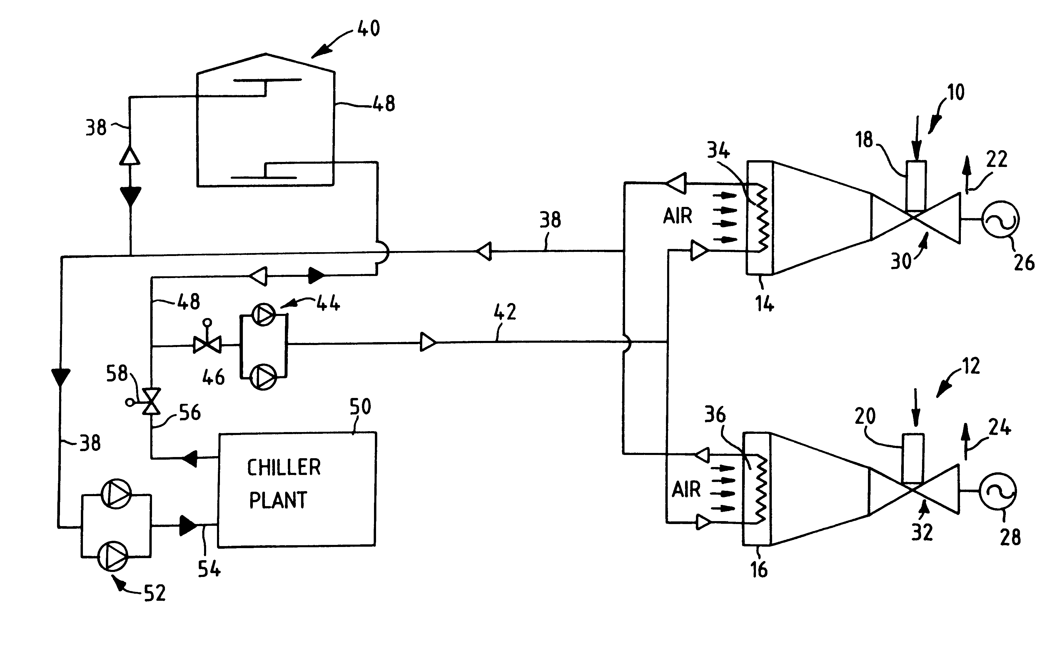
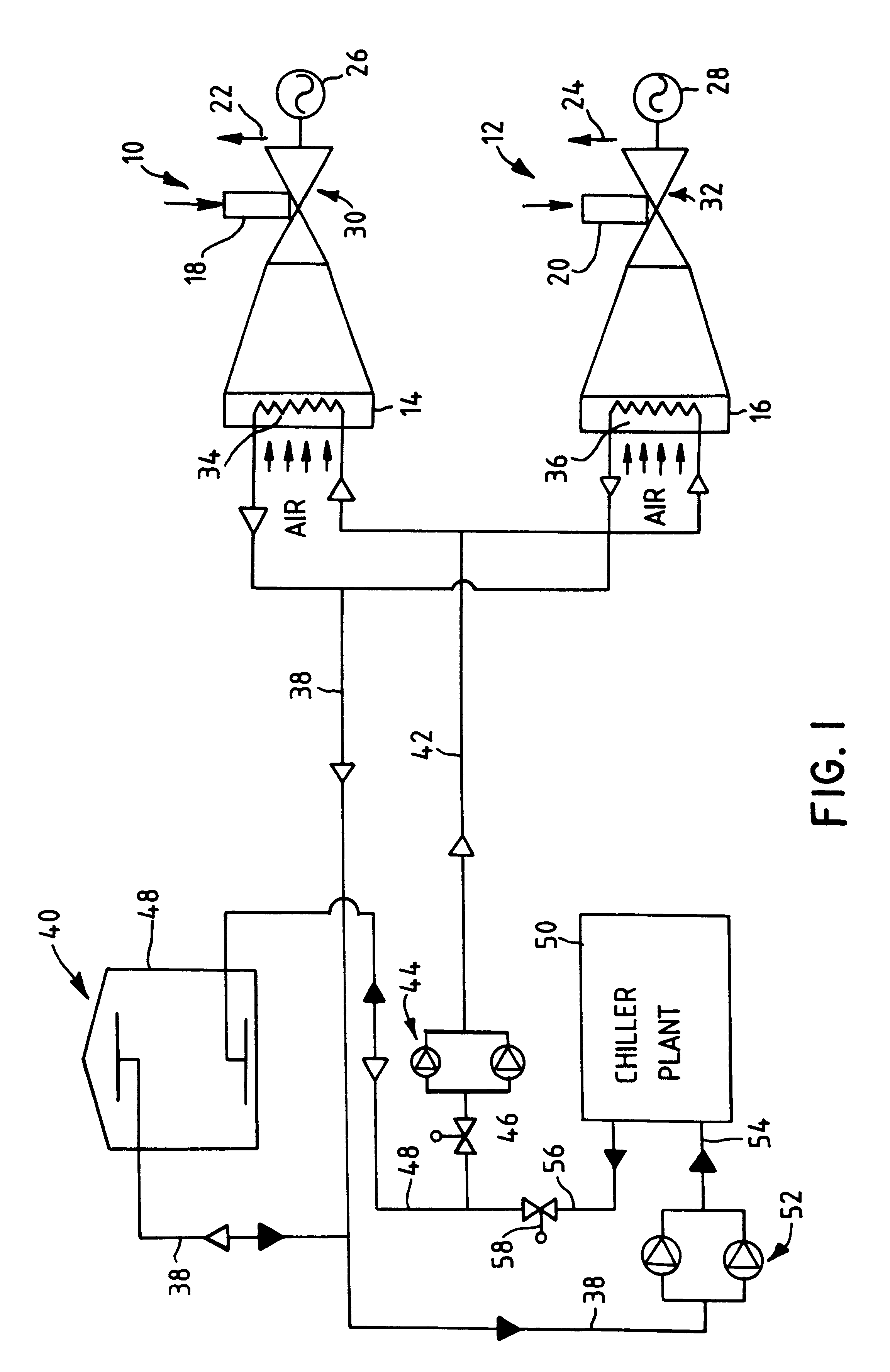
In the embodiment of the present invention shown in FIG. 1, two combustion turbine assemblies 10 and 12 are shown, each respectively including an inlet air cooler 14, 16, a fuel inlet 18, 20, an exhaust 22, 24, and each being mechanically connected to an electrical generator 26, 28. The turbines themselves are shown generally at 30, 32.

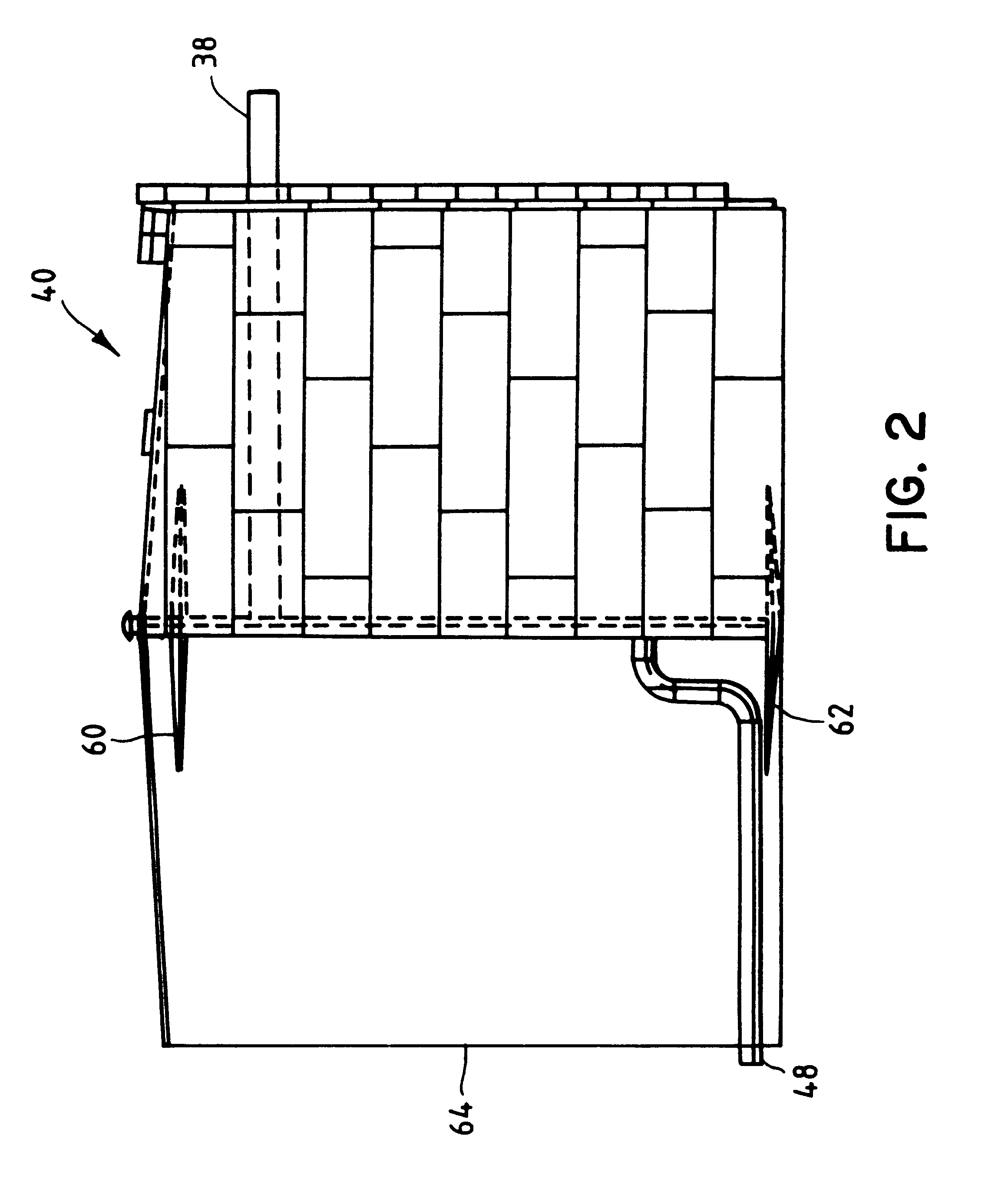
Each air cooler 14, 16, operates as a heat exchanger and employs a respective coil or the like 34, 36 that is connected to a source of cooled fluid. More specifically, the outlets of coils 34, 36 are connected through fluid line 38 to a stratified chilled fluid storage tank, shown generally at 40, and the fluid inlets to the coils 34, 36 are connected to the stratified chilled fluid storage tank 40 via fluid line 42. In the schematic diagram of FIG. 1, solid arrowheads represent a fluid flow direction during off-peak operation times and an open arrowhead represents the fluid flow direction during on-peak operation times. The cooling coil inlet line 42...


PUM


Abstract

Output power and efficiency of combustion turbines, in particular, and combustion engines, in general, are improved by providing cooled intake air to the combustion device. The cooled air is obtained using a thermal energy storage system that has a stratified chilled fluid storage tank. A local or remote chiller plant, possibly already present for use in a thermal energy distribution system, provides the chilled fluid, which can be an aqueous solution of sodium chloride or calcium chloride or both, during off-peak operating times.

Description

1. Field of the InventionThis invention relates generally to improving output and efficiency of combustion engines and, more particularly, to cooling inlet air to combustion turbines.2. Description of the BackgroundInternal combustion engines, including gas turbine engines, also known as combustion turbines, are means of converting fuel such as natural gas, oil, or other liquid or gaseous fuels to electrical, mechanical and / or other forms of useful power output. The available power output of internal combustion engines, however, typically diminishes with rising inlet air temperature. Typical combustion turbines, whose power output is defined as 100% at 15 C. (59.degree. F.) are derated to approximately 85% power output at inlet air temperatures of 90 to 100.degree. F. Conversely, cooling in the inlet air to 40 to 50.degree. F. results in an increased rating of approximately 105% power output. Accordingly, it is of interest, and has been put into practice, to cool the inlet air to co...

Claims


Application Information

Patent Timeline
IPC IPC(8): F02C7/12F02C7/143F02C7/16
CPCF02C7/16F02C7/143
Inventor ANDREPONT, JOHN S.
Owner CHICAGO BRIDGE & IRON CO
Why Eureka
Try Eureka