
Process and apparatus for treating foundry sludge to recover magnesium

a technology of magnesium metal and foundry sludge, which is applied in the purification of alkali metal halides, alkali metal carbonates, alkali metal chlorides, etc., can solve the problems of contaminated sludge, severe environmental problems, and material safety hazards

Inactive Publication Date: 2002-06-25
NORANDA MINES
View PDF5 Cites 4 Cited by
  • Summary
  • Abstract
  • Description
  • Claims
  • Application Information

AI Technical Summary

Problems solved by technology

The disposal of these sludge (containing magnesium metal with chlorides and oxide compounds) presents a problem.
If stockpiled, this material constitutes a safety hazard since it is reactive and readily emits hydrogen and ammonia gas.
This creates a severe environmental issue.
However, calcium sulphate has a relatively high solubility, and it cannot air stripped to a very low level.
The presence of MgSO.sub.4 in the brine is unacceptable, particularly for the electrolytic cells, and
This method also does not remove calcium from the brine.

Method used


Image

  • Process and apparatus for treating foundry sludge to recover magnesium
  • Process and apparatus for treating foundry sludge to recover magnesium
  • Process and apparatus for treating foundry sludge to recover magnesium

Examples


example # 1

EXAMPLE #1

In the first step, 1.5 kg of -10 mesh of dry sludge assaying 20-30% CaCl.sub.2, 12-15% NaCl, 5-10% MgCl.sub.2, <1% KCl, 15-20% MgO, 0.5-2% Fe.sub.2 O.sub.3, Al.sub.2 O.sub.3, MnO, CaO, 5% Mg metal and 1-2% of others was slurried with 3.5 kg of water at 75.degree. C. in less than one hour under good mixing in a first reactor. The reaction was exothermic and the slurry temperature was maintained to 75.degree. C. with a cooling system. Hydrogen and ammonia gas were detected in the off-gas while mixing the sludge with water. Slurry potential never dropped below -800 mV. All chloride compounds dissolved in the first step.

In the second step, the slurry was heated up to 90.degree. C. prior to adjusting the pH to pH 6 with the addition of concentrated hydrochloric acid (1.1 litre of 36% hydrochloric acid) over 60 minutes. The acid was added on demand by controlling the slurry potential to greater than -650 mV. The reaction being exothermic, the temperature was maintained to 90.deg...

example # 2

EXAMPLE #2

In the first step, 1.5 kg of -10 mesh of dry sludge assaying 20-30% CaCl.sub.2, 12-15% NaCl, 5-10% MgCl.sub.2, <1% KCl, 15-20% MgO, 0.5-2% Fe.sub.2 O.sub.3, Al.sub.2 O.sub.3, MnO, CaO, 5% Mg metal and 1-2% of others was slurried with 3.5 kg of water at 75.degree. C. in less than one hour under good mixing in a first reactor. The reaction was exothermic and the slurry temperature was maintained to 75.degree. C. with a cooling system. Hydrogen and ammonia gas were detected in the off-gas while mixing the sludge with water. Slurry potential never dropped below -775 mV. All chloride compounds dissolved in the first step.

In the second step, the slurry was heated to 100.degree.-105.degree. C. prior to adjusting the pH to pH 6 with the addition of concentrated hydrochloric acid (1.09 liters of 36% hydrochloric acid) over 60 minutes. The acid was added on demand by controlling the slurry potential to greater than -650 mV. The reaction being exothermic, the temperature was maintain...


PUM

PropertyMeasurementUnit
pHaaaaaaaaaa
pHaaaaaaaaaa
pHaaaaaaaaaa

Abstract

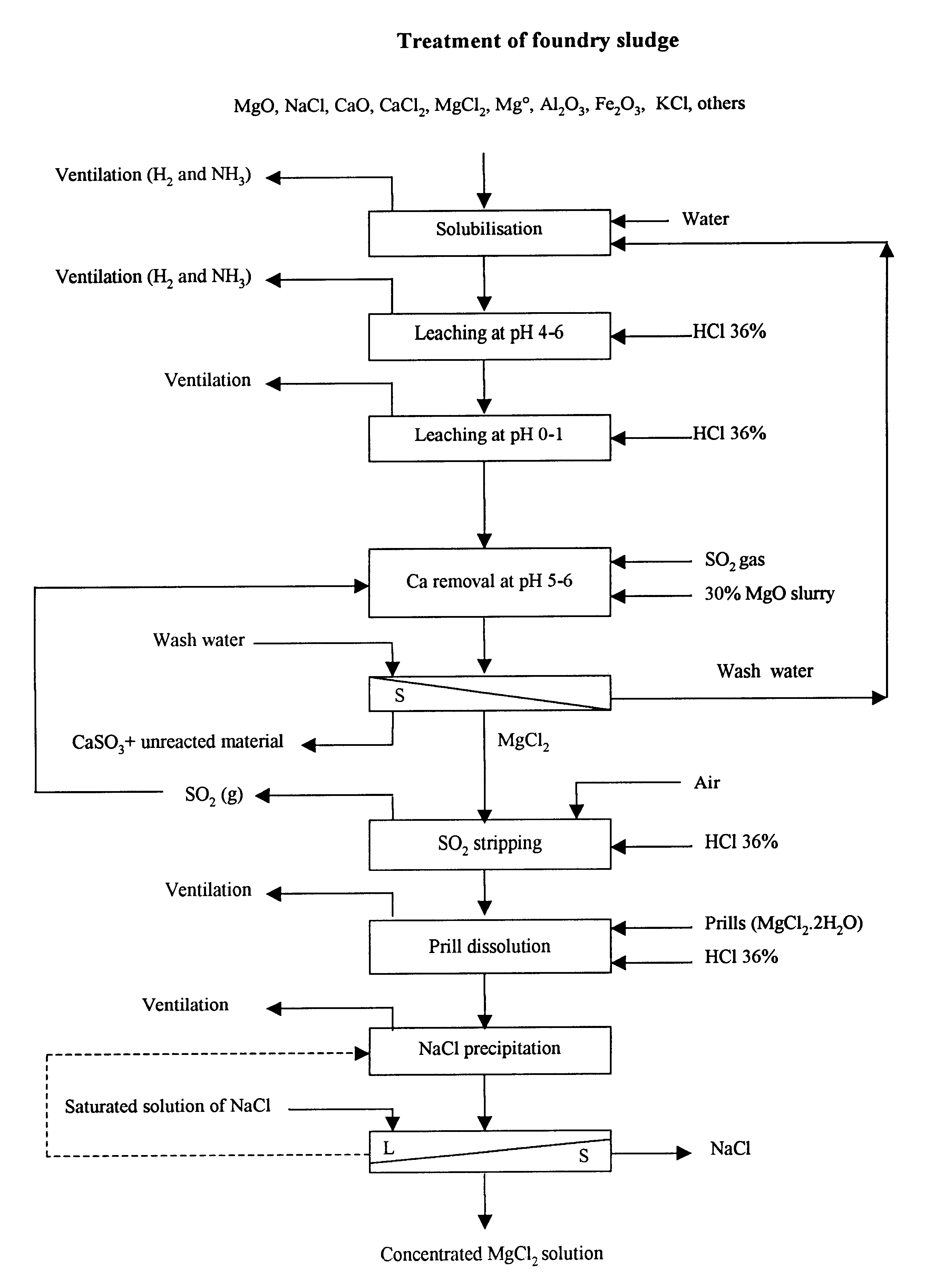
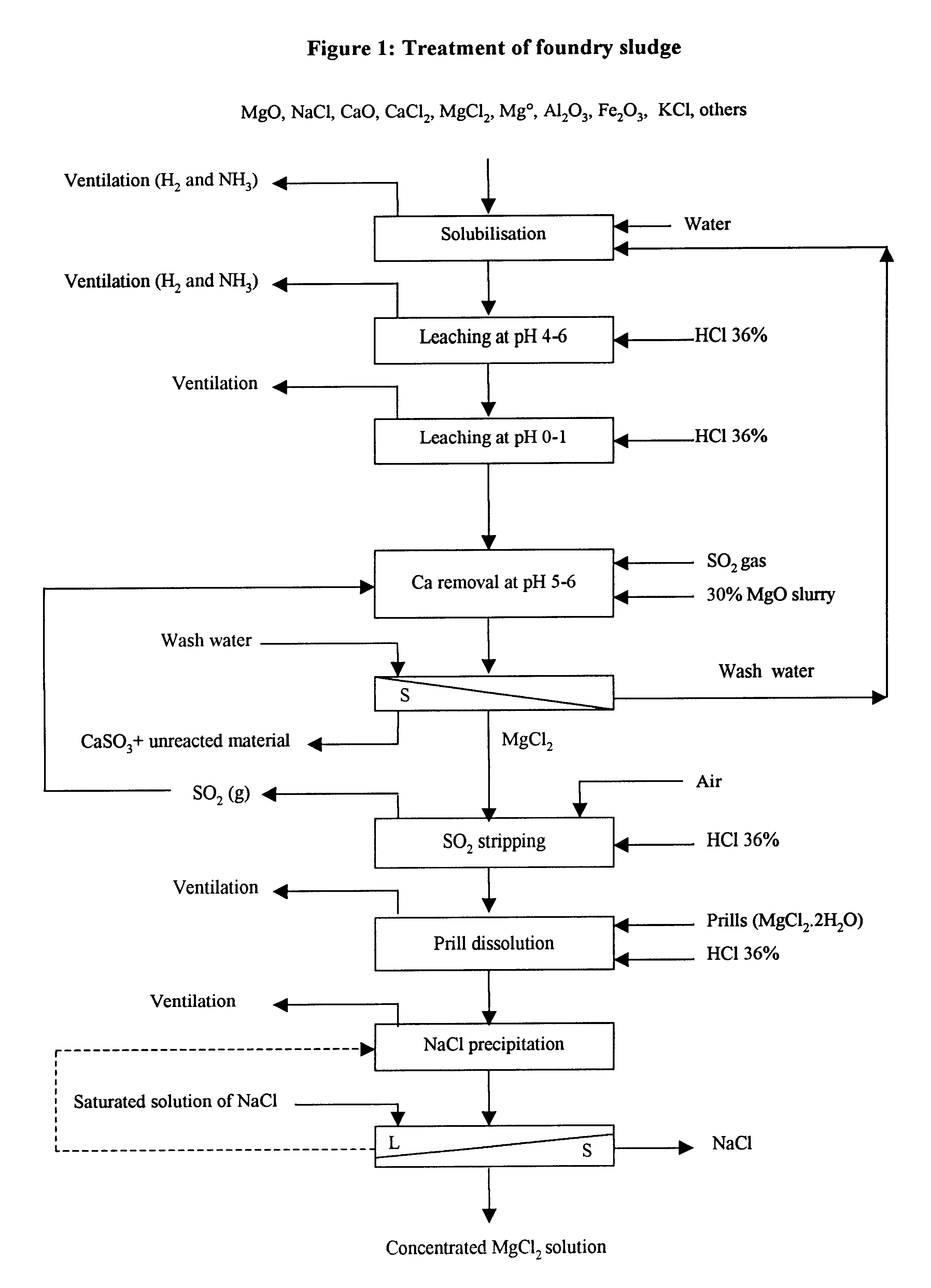
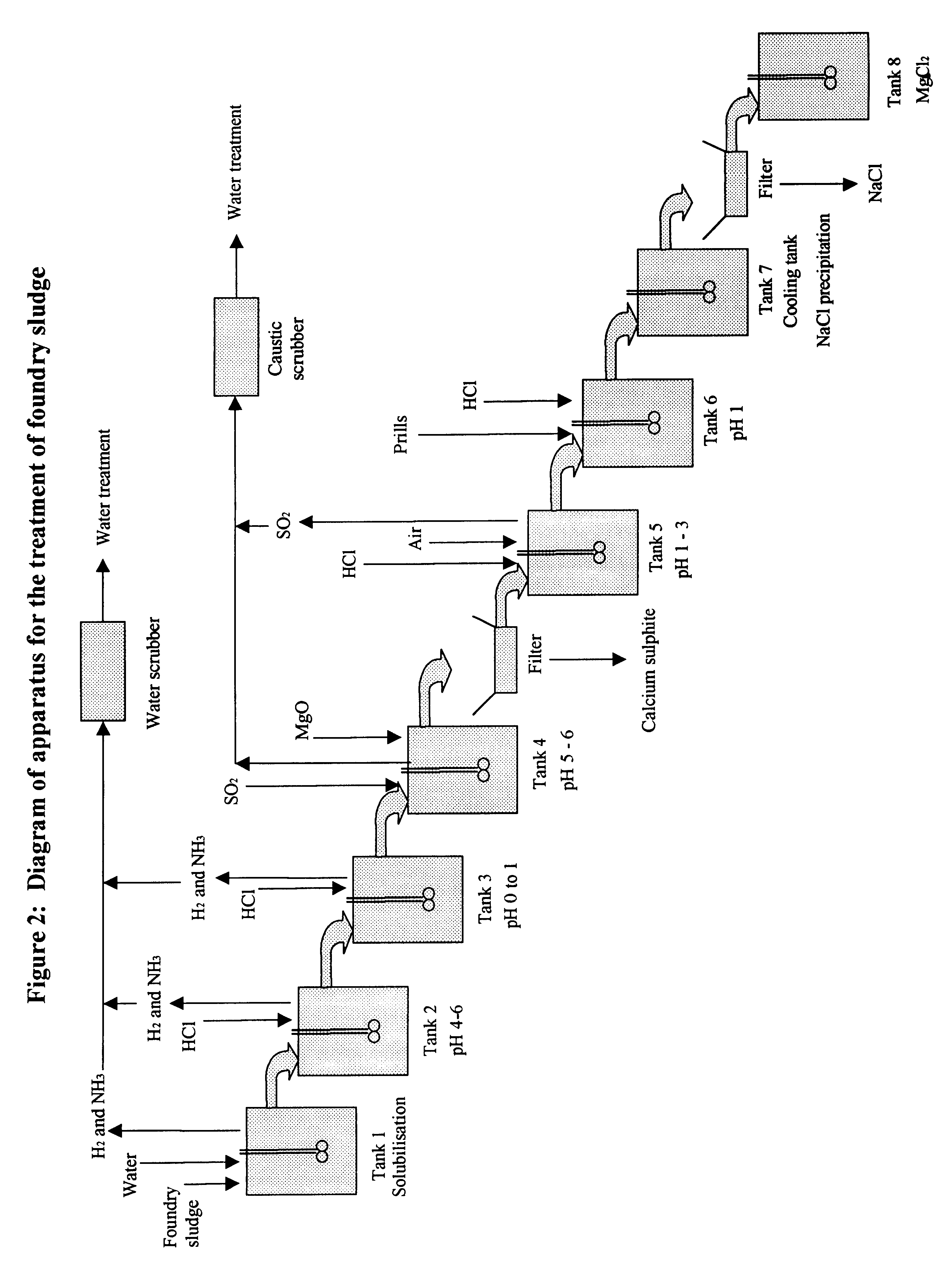
Process and apparatus for recovering magnesium from foundry sludge and cell bleed electrolytes includes structure and / or steps for: (i) dissolving, in a water slurry, soluble chloride compounds in the magnesium-containing material; (ii) acidifying the water slurry to between substantially pH 4 and substantially pH 6; (iii) further acidifying the water slurry to between substantially pH 1 and substantially pH 0, and providing a magnesium chloride solution; (iv) precipitating calcium from the magnesium chloride solution; (v) separating solids from the magnesium chloride solution; (vi) stripping SO2 from the magnesium chloride solution; and (vii) precipitating NaCl from the magnesium chloride solution to provide a concentrated magnesium chloride solution.

Description

1. Field of the InventionThe present invention relates to a new hydrometallurgical process and apparatus for treating foundry sludge and cell bleed electrolyte to recover magnesium as magnesium chloride, while selectively removing calcium and sodium. The present invention also relates to removing calcium and sodium impurities from brines of magnesium chloride.2. Related ArtIn the production of pure magnesium metal, various sludge are generated from the foundry and the electrolytic cell. For example, pure magnesium metal may be cast in a casting furnace, and magnesium alloys may be cast in an alloying furnace. Both of these furnaces will produce residues called sludge which contain mainly magnesium metal, magnesium chloride, sodium chloride, calcium chloride, calcium oxide, and magnesium oxide. This electrolytic cell also produces cell bleed electrolyte containing magnesium metal and various other compounds.The disposal of these sludge (containing magnesium metal with chlorides and o...

Claims


Application Information

Patent Timeline
Patent Type & Authority Patents(United States)
IPC IPC(8): C01D3/08C01D3/00C01F5/00C01F11/00C01F11/48C01F5/30C22B7/00C22B26/22C22B3/44C22B3/00C22B26/00
CPCC01D3/08C01F5/30C01F11/48C22B26/22C22B3/44C22B7/007C01P2004/61Y02P10/20
Inventor WHITE, CARL W.GUIMONT, JEANPINARD, DENYSMONETTE, SERGE
Owner NORANDA MINES
Learn More