Method and apparatus for assessment of changes in intracranial pressure

a technology of intracranial pressure and measurement method, applied in the field of measuring and monitoring of intracranial pressure changes, can solve the problems of tissue edema, techniques that do not include techniques nor refinements to remove extracranial effects from measurements,

Inactive Publication Date: 2002-07-02
NASA
View PDF8 Cites 37 Cited by
  • Summary
  • Abstract
  • Description
  • Claims
  • Application Information

AI Technical Summary

Benefits of technology

to provide a non-invasive method and device for measuring change in intracranial distances which removes extracranial effects from the measurements, and to provide calibration techniques that enable that change in skull dimension to be related to the change in intracranial pressure. It is a further object to provide a non-invasive method for monitoring changes in intracranial pressure in human patients.

Problems solved by technology

A prior method of measuring intracranial pressure included pulse phase-locked ultrasonic technology but this method did not include techniques nor refinements to remove extracranial effects from the measurements.
Such techniques, however, are also subject to the same problems associated with surface tissue edema and perfusion, similar to the ultrasonic technique.
Thus, although prior devices and methods are generally non-invasive, they are affected by surface tissue changes.
This would make the techniques invasive, although not as invasive as drilling a hole through the cranium for insertion of a probe.

Method used


Image

  • Method and apparatus for assessment of changes in intracranial pressure
  • Method and apparatus for assessment of changes in intracranial pressure
  • Method and apparatus for assessment of changes in intracranial pressure

Examples


second embodiment

the present invention is shown in FIG. 3. This embodiment works similarly to the first, except that a voltage controlled oscillator 200 generates oscillator frequency changes to bring about quadrature for each echo. As in the preferred embodiment, the .div.P circuit 170, the bi-stable circuit 180 and the analog switch 190 work together to alternately select which signal (106 or 116) controls quadrature, in this case by controlling frequency. For this second embodiment, there is an inherent instrument error, due to electronics sensitivity to frequency changes. This error is typically no more than 15%. The equation for calculation of path expansion is, for the second embodiment: ##EQU14##

where f and .DELTA.f are measured by the frequency counter 162.

third embodiment

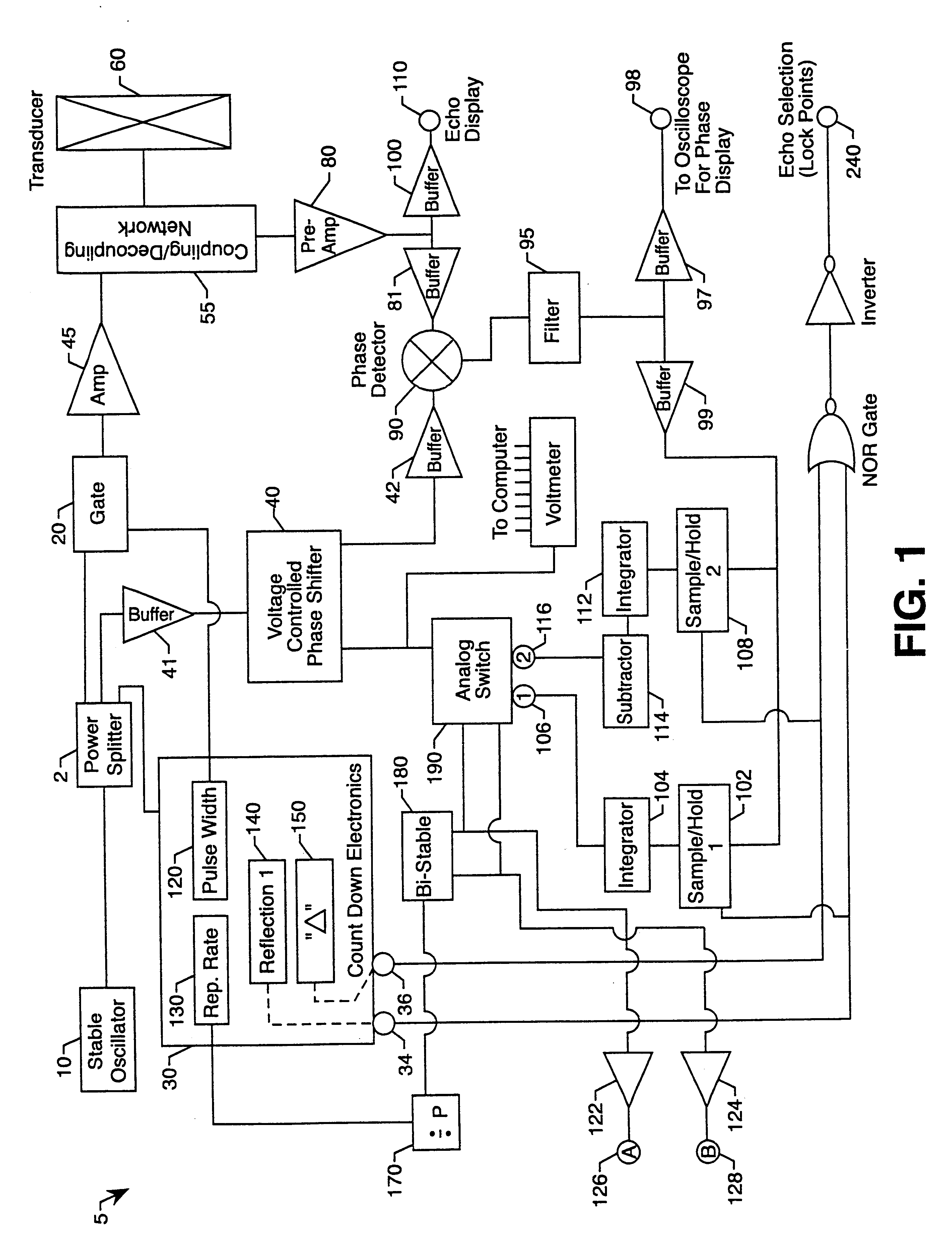
the present invention, as shown in FIG. 7, offers the advantages of near simultaneous measurement of both echoes, avoidance of switching transients, shorter response time, and requires a smaller dose of ultrasonic power. This embodiment is similar to the embodiment of FIG. 1, except for: sample and hold 1102 captures the phase comparison of the echo 1 signal with the stable oscillator signal fed through the voltage controlled phase shifter 140 and holds its value. Sample and hold 2108 captures the phase comparison of the echo 2 signal with the stable oscillator signal fed through voltage controlled phase shifter 243 and holds its value. These signals are then fed to their respective integrators 104, 112 so that:

a) a phase shifter control voltage is developed by integrator 1104 that will produce quadrature with echo 1 signal, while, nearly simultaneously;

b) a phase shifter control voltage is developed by integrator 2112 that will give quadrature with echo 2 signal; and

c) the control ...


PUM


Abstract

A non-invasive method and apparatus for monitoring changes in intracranial pressure which removes extracranial effects from the measurements. The method and apparatus can include the supplying of a fixed frequency electrical output to a transducer coupled to the patient's head, thereby generating an acoustical tone burst in the patient's head which generates a first echo and a second echo, the first echo reflecting from a first interface in the side of the patient's head coupled to the transducer, and the second echo reflecting from a second interface at the opposite side of the patient's head. The first and second echoes are received by the transducer which can generate a first electrical signal and a second electrical signal, wherein the first and second electrical signals vary in accordance with the corresponding first and second echoes. The counterbalancing phase shifts required to bring about quadrature between each of the first and second electrical signals and the fixed frequency electrical output can be measured, and values for the change in intracranial distance based on the changes in the counterbalancing phase shifts can be obtained.

Description

1. Field of the InventionThis invention relates to measuring and monitoring of intracranial pressure changes in human patients, and more particularly to a non-invasive method and device for monitoring changes in intracranial pressure which removes extracranial effects from the measurements.2. Background of the InventionA prior method of measuring intracranial pressure included pulse phase-locked ultrasonic technology but this method did not include techniques nor refinements to remove extracranial effects from the measurements.Another prior method includes an ultrasonic means to measure expansion of a pre-selected path through the cranial cavity by means of placement of a 500 KHz ultrasonic transducer at an appropriate location on the skull. In this technique, the measurement includes not only skull expansion, but also includes effects of edema and perfusion of tissues between the skin and the skull. This perfusion can result in measurements that are much larger than the path change...

Claims


Application Information

Patent Timeline
Patent Type & Authority Patents(United States)
IPC IPC(8): A61B5/03A61B8/08
CPCA61B5/031A61B8/0808
Inventor YOST, WILLIAM T.CANTRELL, JOHN H.
Owner NASA
Why Eureka
Try Eureka