3-D imaging multiple target laser radar

a laser radar and multiple target technology, applied in the direction of reradiation, distance measurement, instruments, etc., can solve the problems of cumbersome mechanical scanners, complex pixel-registration computer processing, slow rastering process, etc., and achieve the effect of accurate determination

Inactive Publication Date: 2002-07-02
CONTINENTAL AUTONOMOUS MOBILITY US LLC
View PDF4 Cites 176 Cited by
  • Summary
  • Abstract
  • Description
  • Claims
  • Application Information

AI Technical Summary

Benefits of technology

It is further the object of the present invention to provide improved sensors which detect and store laser-pulse, target-reflected, transit-time and / or target-reflected laser pulse amplitude information on a processing-electronics unit cell array from which the ranges and 3-D shape of multiple targets or obscured targets can be accurately determined.

Problems solved by technology

Rastering is a slow process, particularly for large pixel-array sizes, and it requires cumbersome mechanical scanners and complex pixel-registration computer processing.

Method used


Image

  • 3-D imaging multiple target laser radar
  • 3-D imaging multiple target laser radar
  • 3-D imaging multiple target laser radar

Examples


Embodiment Construction

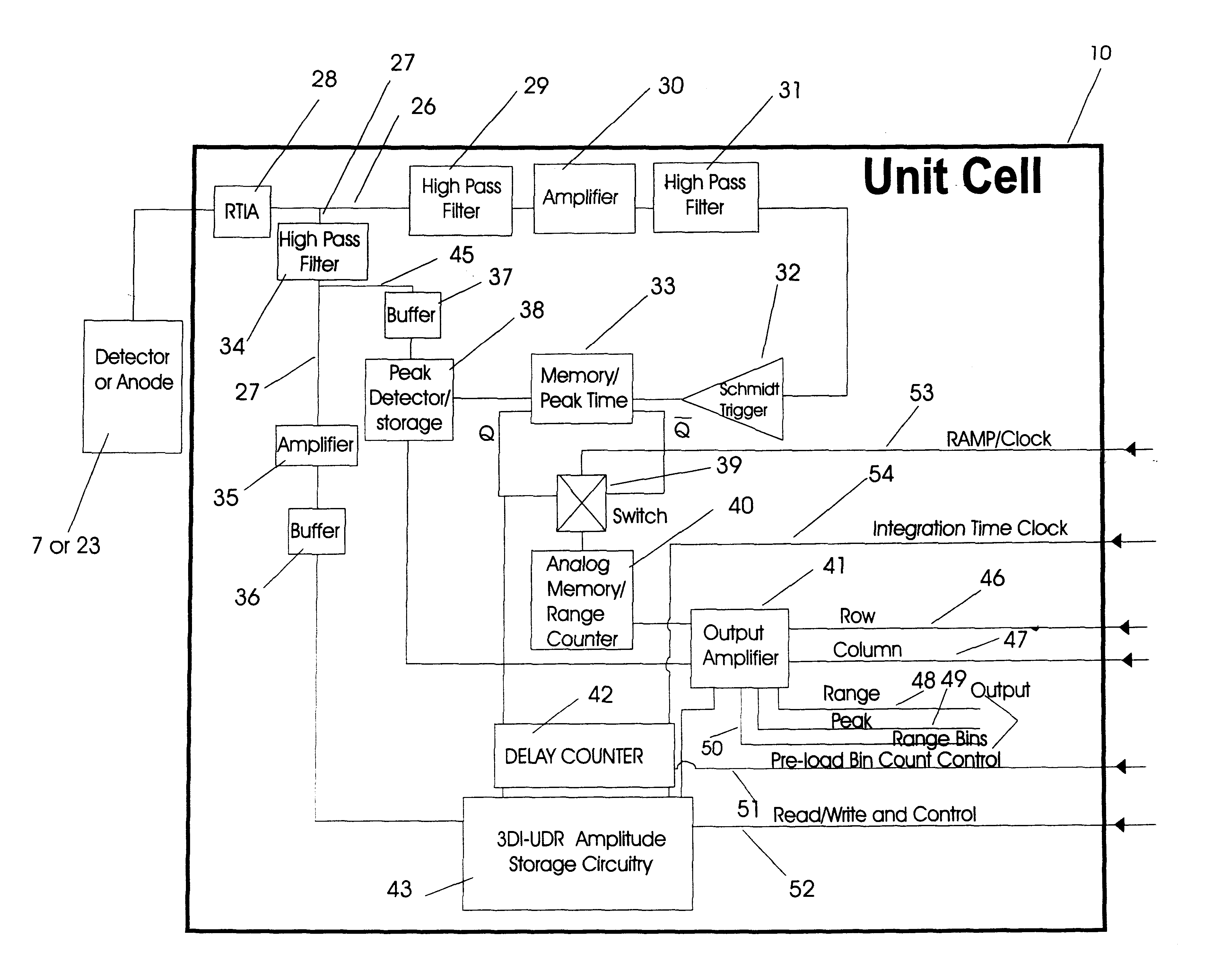
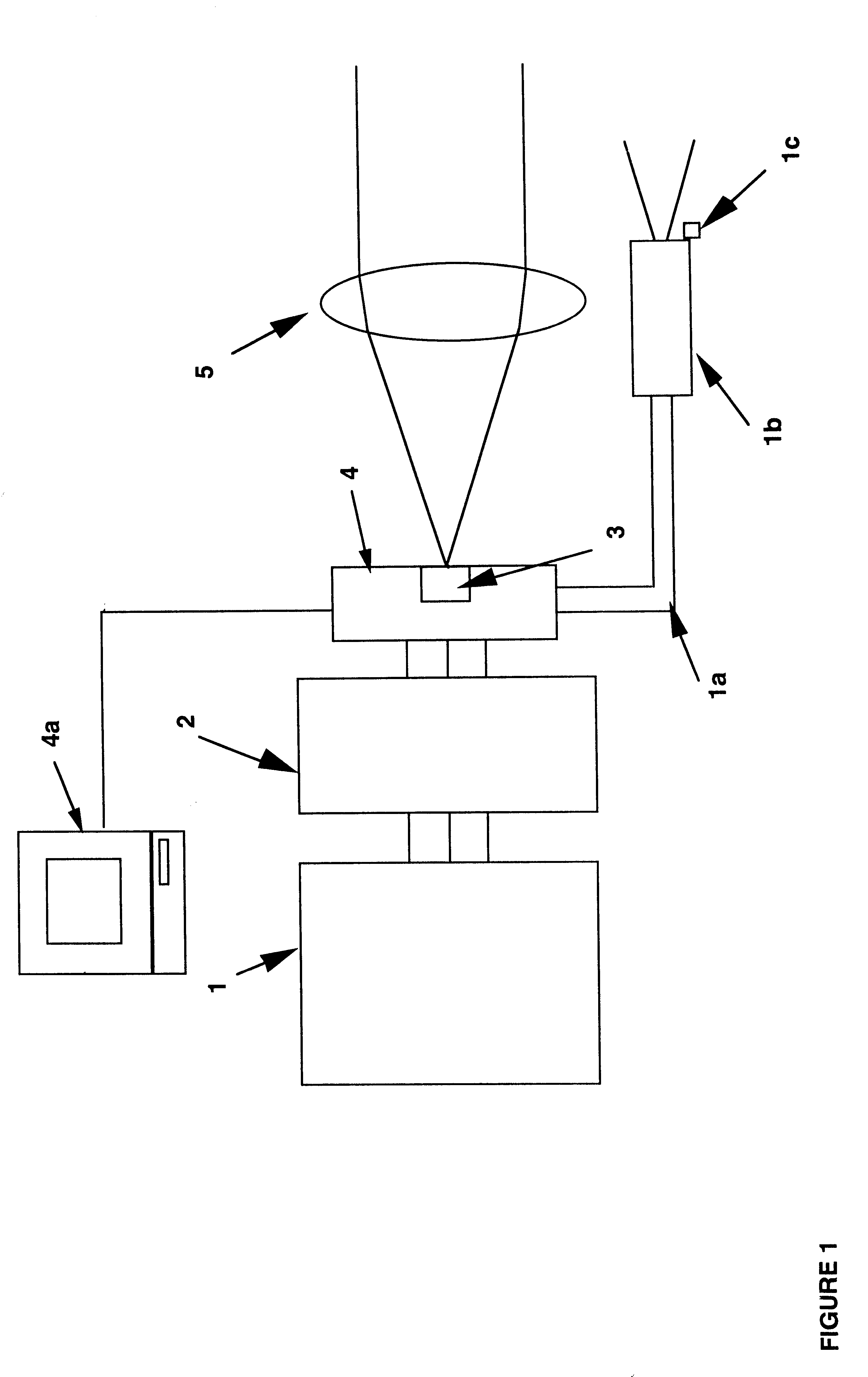
A preferred embodiment of the present invention, the Penetrating 3-D Ladar (PDAR) imaging system depicted in FIG. 1, is designed to produce three-dimensional image data (area and range) from a single laser pulse reflected from objects in the atmosphere, located in or behind obscurants, using transit time and / or amplitude information, and process the data to form a three dimensional image. Six parts make up the preferred embodiment of the invention; a pulsed laser 1, with delivery system 1a, collimator 1b and laser transmission detector 1c; the data processing and laser control system 2; the sensor 3, and associated Drive and Output Electronics 4, and the optics 5. The Drive and Output Electronics 4 is electrically connected to an image processing computer 4a.

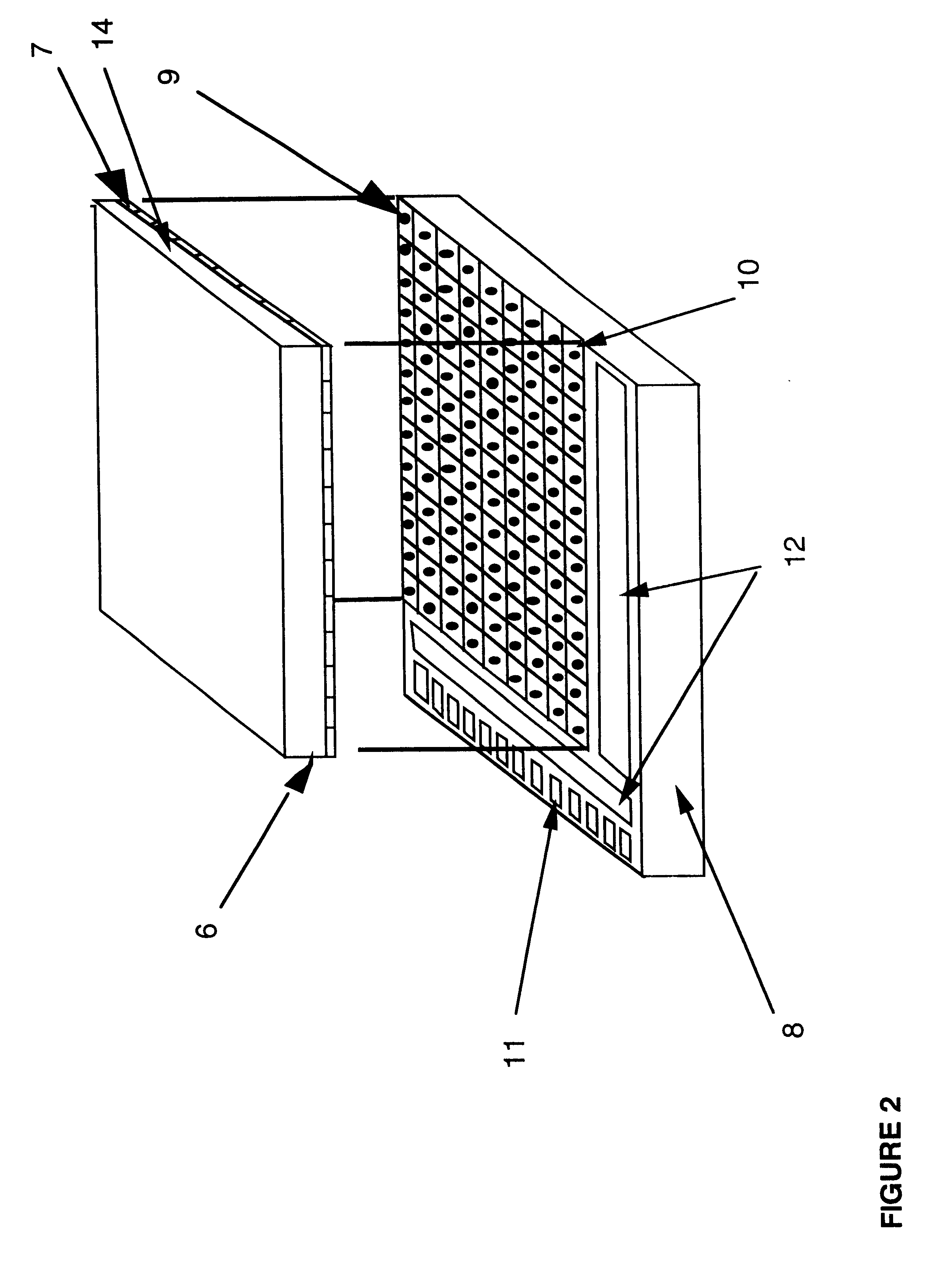
FIG. 2 shows one sensor design 3, a hybrid sensor, in greater detail. It consists of a detector array chip 6, composed of individual detectors 7, the laser radar processor chip 8, and conducting bumps 9, which electrically conne...


PUM


Abstract

A three dimensional imaging device is presented which uses a single pulse from a pulsed light source to detect objects which are obscured by camouflage, fog or smoke but otherwise enveloped by a light-transmitting medium. The device simultaneously operates in two modes, light reflected from the nearest object is processed to form a three-dimensional image by an array of pixels. This first image is based upon the light-pulse transit time recorded in each pixel. Each pixel also contains a high-speed analog memory that sequentially stores reflected signals at a repeated time interval. The first reflection acts as a time base that controls when the analog memory begins or ends the storage sequence. The first return could be from a camouflage net and the amplitudes of the return signals, after the first return, would then be from objects behind the net. Computer processing these amplitudes reveals the three-dimensional nature of the obscured objects.The device consists of the pulsed light source, optics for collecting the reflected light, a sensor for detecting the light and converting it to electrical data, drive and output electronics for timing and signal conditioning of data generated by the sensors and a computer for processing the sensor data and converting it to a three dimensional image. The sensor collects and processes the light data in a unique manner, first converting it to electricity by a number of alternate detector technologies and then using integrated circuit chips which consist of a two dimensional array of electronic pixels also called unit cells. The two dimensional array defines two dimensions of the image. Stored within each unit cells is data associated with the third dimension, ranges of targets, and amplitudes of target reflections. This data is read out of the integrated circuit chip in the time interval between laser pulses to a processing computer. The processing computer corrects the data and, by means of computer algorithms specific to the device, converts the data to a three-dimensional image of one or more targets. This image may be viewed or processed electronically to isolate targets.

Description

This invention relates to a laser radar vision apparatus capable of producing three-dimensional images of distant targets located behind reflective or absorbing but penetrable barriers such as camouflage and obscuring smoke. In particular, this invention relates to a multiple pixel, electronic apparatus for capturing three-dimensional images of distant targets, within obscurants, at high-spatial and high-range resolution in the atmosphere or in space with a single laser pulse, using a laser-reflection generated trigger.This application is a continuation-in-part of U.S. patent application Ser. No. 08 / 665,738, Filed Jun. 19, 1995, 3D Now U.S. Pat. No. 6,133,989 which is a CIP of Ser. No. 08 / 015,623, Now U.S. Pat. No. 5,446,529 Imaging Laser Radar. Laser radars (ladars) determine range in the atmosphere by measuring the transit time of a laser pulse from the transmitter / receiver to a partially or fully reflective target and dividing by twice the velocity of light in the atmospheric med...

Claims


Application Information

Patent Timeline
Patent Type & Authority Patents(United States)
IPC IPC(8): G01S17/00G01S17/89G01S7/486G01S7/48G01S7/481G01S7/4863G01S17/894
CPCG01S7/4816G01S7/4863G01S17/89G01S17/894
Inventor STETTNER, ROGERBAILEY, HOWARD W.
Owner CONTINENTAL AUTONOMOUS MOBILITY US LLC
Why Eureka
Try Eureka