Bundled monocapillary optics

a monocapillary, optics technology, applied in the field of xray optics, can solve the problems of inability to produce small spots, relatively high cost, and inability to form very small focused or collimated beams

Inactive Publication Date: 2002-07-02
HIRSCH GREGORY
View PDF1 Cites 8 Cited by
  • Summary
  • Abstract
  • Description
  • Claims
  • Application Information

AI Technical Summary

Problems solved by technology

This type of optic is not capable of producing spots smaller than approximately 500 microns; the diameter of each fiber.
Their main disadvantage is their relatively high cost, and their inability to form very small focused or collimated beams.
The smallest beams have been produced by the condenser type optics, although the small working distance from the exit aperture can be a disadvantage.
There has been some progress in forming glass capillaries with paraboloidal or ellipsoidal shapes, but the slope errors and straightness of the capillary shapes have been difficult to reliably reproduce.
It has also not been feasible to coat the inside of these very small capillaries with a different material to enhance the reflectivity.
1) It is possible to reproducibly generate almost any desired shape for the individual capillary channels on demand.
2) The process permits wide latitude in the selection of materials of the capillary bores for optimizing the reflectivity of the radiation being used. This can even include multilayer coatings.
3) A highly absorbing material can surround the reflecting layer which minimizes scattered-radiation background.
4) The manufacturing process does not rely on drawing the capillary materials at elevated temperatures which can be difficult to control, and often introduces deformation.

Method used


Image

  • Bundled monocapillary optics
  • Bundled monocapillary optics
  • Bundled monocapillary optics

Examples


Embodiment Construction

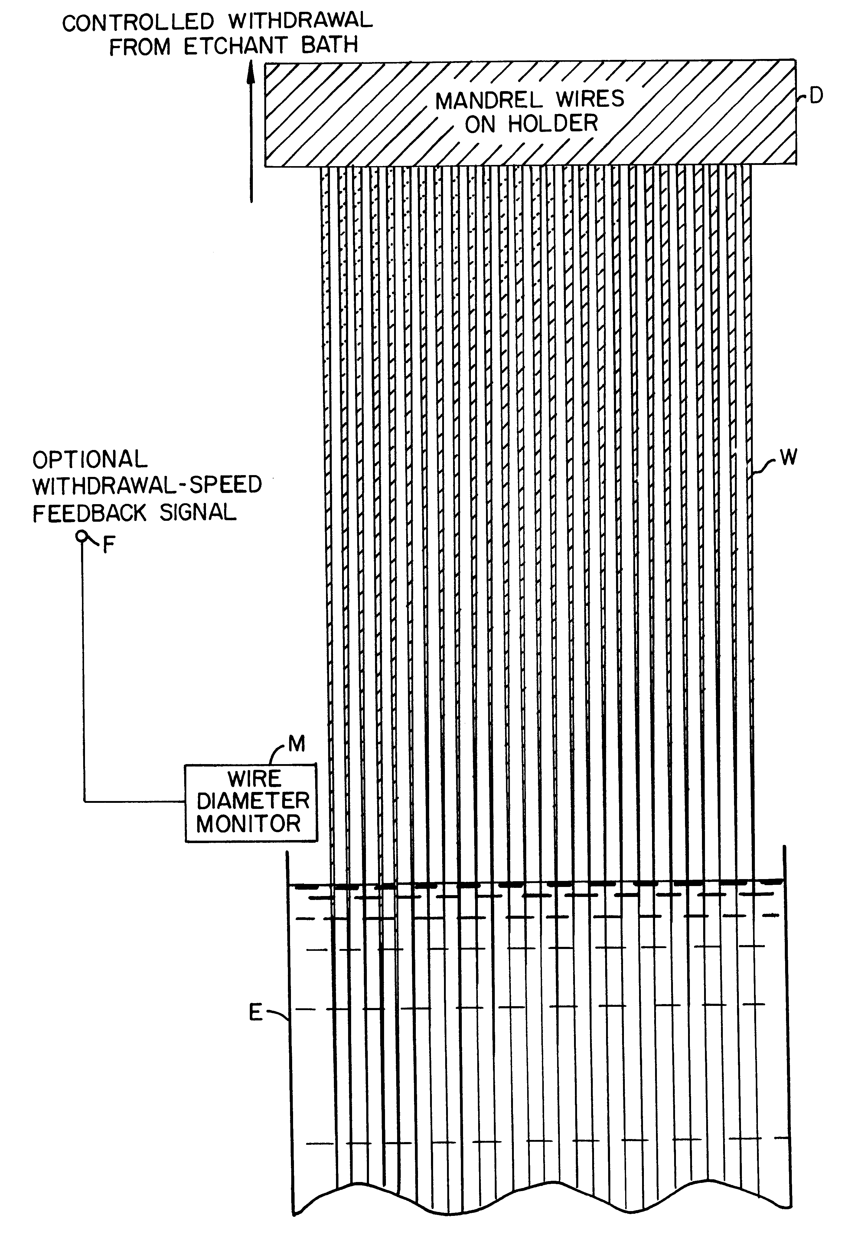
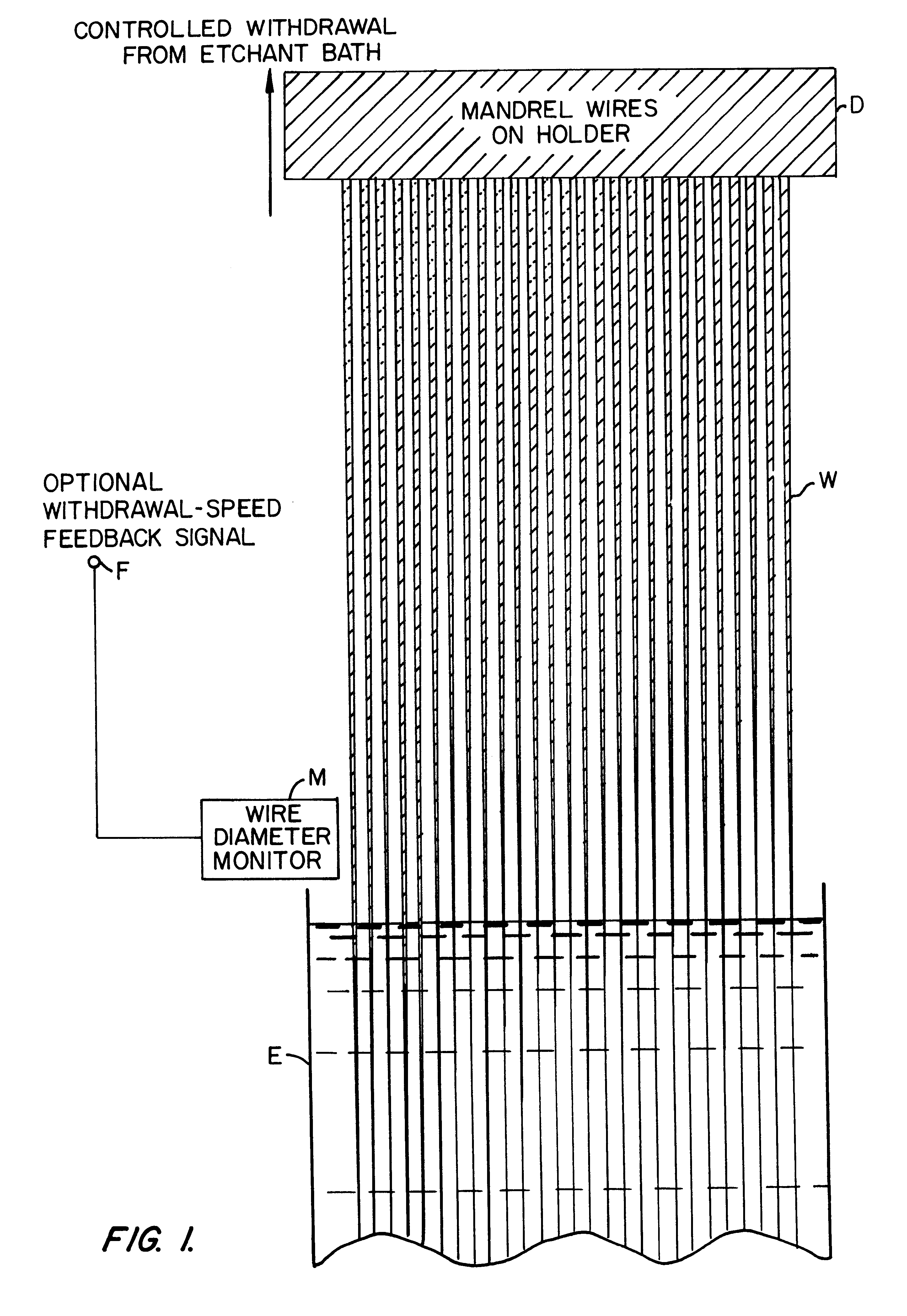
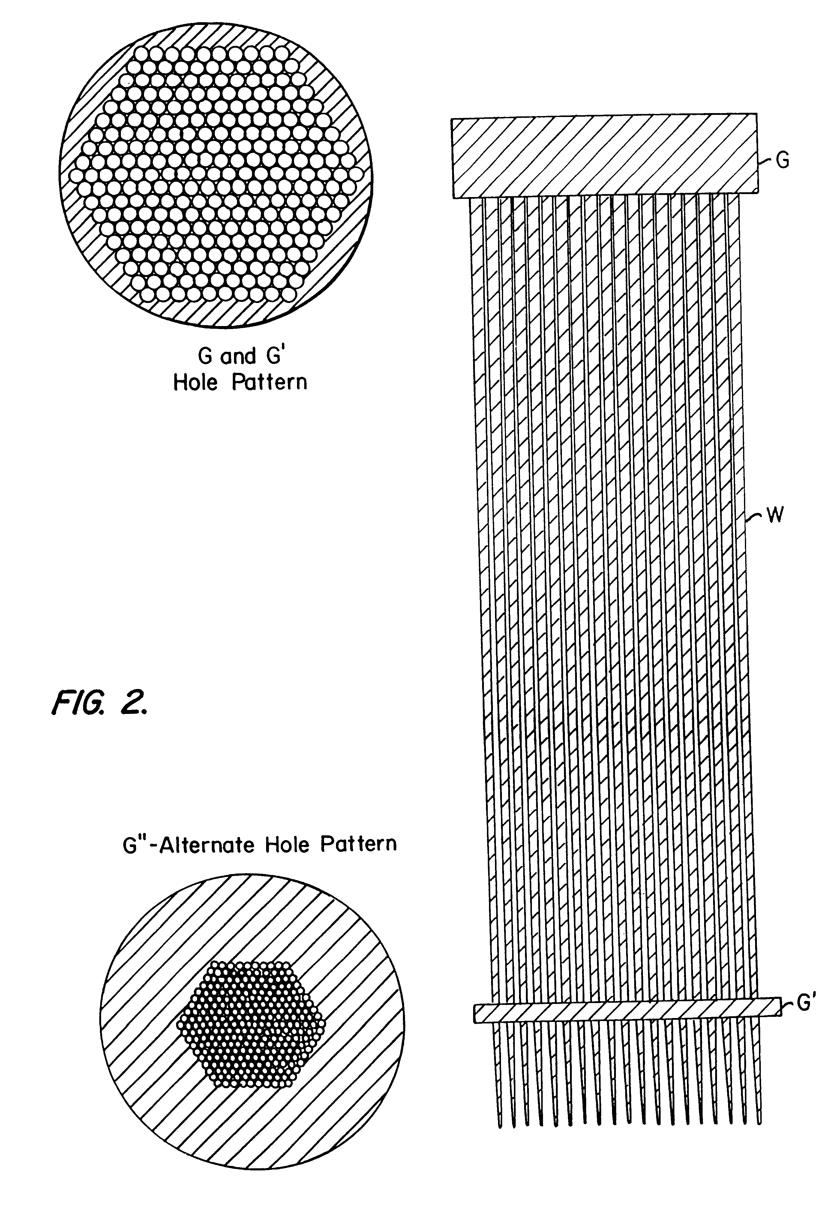
U.S. Pat. No. 5,772,903 previously described a fabrication technique for creating tapered monocapillary optics. That patent disclosed a method for creating capillaries with the desired taper profiles on demand which could include paraboloidal, ellipsoidal, conical, or other figures. It is also possible to have a combination of different taper shapes on a single wire, such as a linearly-tapered section followed by a paraboloidal or ellipsoidal taper. The basic capillary formation process described in that patent is the following: A metal or glass wire is etched with great precision to have a taper with the shape of the desired final capillary-optics bore. By controlling the rate of removal of the wire from an etchant bath, the precisely controlled taper is produced. The wire velocity can be regulated using a closed-loop control system which uses a sensor to measure the wire diameter or slope of the wire as it leaves the etchant for feedback control. The etched wire undergoes a treatm...


PUM

PropertyMeasurementUnit
poweraaaaaaaaaa
critical angleaaaaaaaaaa
surface roughnessaaaaaaaaaa

Abstract

A plurality of glass or metal wires are precisely etched to form the desired shape of the individual channels of the final polycapillary optic. This shape is created by carefully controlling the withdrawal speed of a group of wires from an etchant bath. The etched wires undergo a subsequent operation to create an extremely smooth surface. This surface is coated with a layer of material which is selected to maximize the reflectivity of the radiation being used. This reflective surface may be a single layer of material, or a multilayer coating for optimizing the reflectivity in a narrower wavelength interval. The collection of individual wires is assembled into a close-packed multi-wire bundle, and the wires are bonded together in a manner which preserves the close-pack configuration, irrespective of the local wire diameter. The initial wires are then removed by either a chemical etching procedure or mechanical force. In the case of chemical etching, the bundle is generally segmented by cutting a series of etching slots. Prior to removing the wire, the capillary array is typically bonded to a support substrate. The result of the process is a bundle of precisely oriented radiation-reflecting hollow channels. The capillary optic is used for efficiently collecting and redirecting the radiation from a source of radiation which could be the anode of an x-ray tube, a plasma source, the fluorescent radiation from an electron microprobe, a synchrotron radiation source, a reactor or spallation source of neutrons, or some other source.

Description

This invention relates to the use of optics to produce a directed beam of radiation by grazing-incidence reflection. More particularly, an optical element is disclosed which is produced by assembling a collection of separate tapered-monocapillary optical elements to form a polycapillary optic. The individual monocapillary channels are created in a batch process which allows for the optimization of the shape, smoothness, and material choice of the radiation-reflecting interior surfaces. The resultant optics can be used to produce either a collimated beam or a focused spot of photons, neutrons, or charged particles. In the case of photons, the use of x-rays is the most important application.In recent years, there have been dramatic developments in the field of x-ray optics. Many different types of optical elements have been introduced or improved for the manipulation of short wavelength photons. In the specific area of focusing optics, several different types of lenses and focusing mi...

Claims


Application Information

Patent Timeline
Patent Type & Authority Patents(United States)
IPC IPC(8): C03C25/68G02B6/10G02B6/04G02B6/26G02B6/36G02B6/42
CPCC03C25/68G02B6/04G02B6/10G02B6/262G02B6/3628G02B6/4203Y10S359/90
Inventor HIRSCH, GREGORY
Owner HIRSCH GREGORY
Why Eureka
Try Eureka