
Operating method of fluidized-bed incinerator and the incinerator

a technology of fluidized bed and incinerator, which is applied in the direction of fluidised bed combustion apparatus, lighting and heating apparatus, combustion types, etc., can solve the problems of inconvenient combustion, waste of extra air, and parts of the freeboard becoming too hot,

Inactive Publication Date: 2002-07-16
MITSUBISHI HEAVY IND LTD
View PDF26 Cites 32 Cited by
  • Summary
  • Abstract
  • Description
  • Claims
  • Application Information

AI Technical Summary

Problems solved by technology

Since the combustion energy required to incinerate raw garbage or sludge is likely to vary, parts of the freeboard may become too hot.
More exhaust gas is produced, and the extra air is wasted.
If the substance is less dense than the bed, when it is loaded into the chamber via the freeboard it will float on the surface of the fluidized sand on the very top of bubbling region, and the temperature within that region will not be conducive to effective combustion.
This imposes limitations on the maximum load which are not present when combustion can be extended effectively to the entire lower portion of the bed, including the bubbling region in the lower half of the air bubble bed and the dense layer below it.
Moreover, if combustion is achieved only in the upper portion of the aforesaid sand bed, the volatile component of the substance to be burned will be propelled through the splash region above the bed and combusted in the freeboard.
As a result, the temperature in the furnace will be unstable.
Another problem which can occur is that the waste product which falls onto the sand on top of the aforesaid bubbling region may not break up effectively.
This results in some portions remaining uncombusted and leads to improper fluidization.
Also, waste matter like raw garbage and sewage sludge contains a high volume of volatile components.
This causes the temperature of the exhaust gases to be too high.
In particular, if the temperature of the sand in the fluidized bed drops below 750.degree. C., the combustion rate in the bed will decrease, increasing the prospect of unstable combustion.
When the volatile component is combusted in the aforesaid freeboard, it cannot contribute to maintaining the temperature of the sand.
As we have noted, prior art air bubble-type fluidized bed incinerators experience problems due to the differing fuel quality of different waste substances.
If the waste contains a great deal of moisture, the temperature of the sand will drop.
There was no effective way to address these problems in the prior art.
In addition, prior art techniques could not mitigate the problem of temperature fluctuation in the freeboard caused by varying fuel quality in different parts of the waste material.
However, since some or in some cases almost all of the accelerant would immediately sublimate, it would combust in the freeboard without contributing to the temperature of the sand.
The accelerant was thus combusted to no purpose, which had a deleterious effect on the fuel cost.
But a circulating bed lacks a distinct dense layer (dense bed) in its lower portion, so its capacity to absorb load fluctuations is negligible, and the characteristics of the exhaust gases are likely to be unstable.
Since these coarse particles, the fluidizing medium in the heavy bed, experience significant abrasion, they must be replenished frequently, which complicates the maintenance of the furnace.
Also, the use of the aforesaid coarse particles which are prone to abrasion results in a loss of stability due to variations of the particle size ratio.
Just how much the capacity of the system can be increased in the ways described above is limited by the size of the fine and coarse particles and by how well the coarse particles can be fluidized, which depends largely on the aforesaid speed of fluidization.
There is also a tendency for changes in the system to result in unstable reaction conditions.
Its maintenance is complicated by the requirement that the coarse particles be replenished very frequently, and the use of coarse particles which are prone to abrasion results in variation in the particle size ratio, which causes the system to be unstable.
Furthermore, even the fact that the device has two gas inlets results in virtually no better control of the suspension density of the fine particles in the entraining bed.
Japanese Patent Publications (Koukoku) 59-13644 and 57-28046 offer designs which can be applied to this sort of fluidized bed incinerator and its operating method, but these, too, lack any means to address the problem areas described above.

Method used


Image

  • Operating method of fluidized-bed incinerator and the incinerator
  • Operating method of fluidized-bed incinerator and the incinerator
  • Operating method of fluidized-bed incinerator and the incinerator

Examples


first preferred embodiment

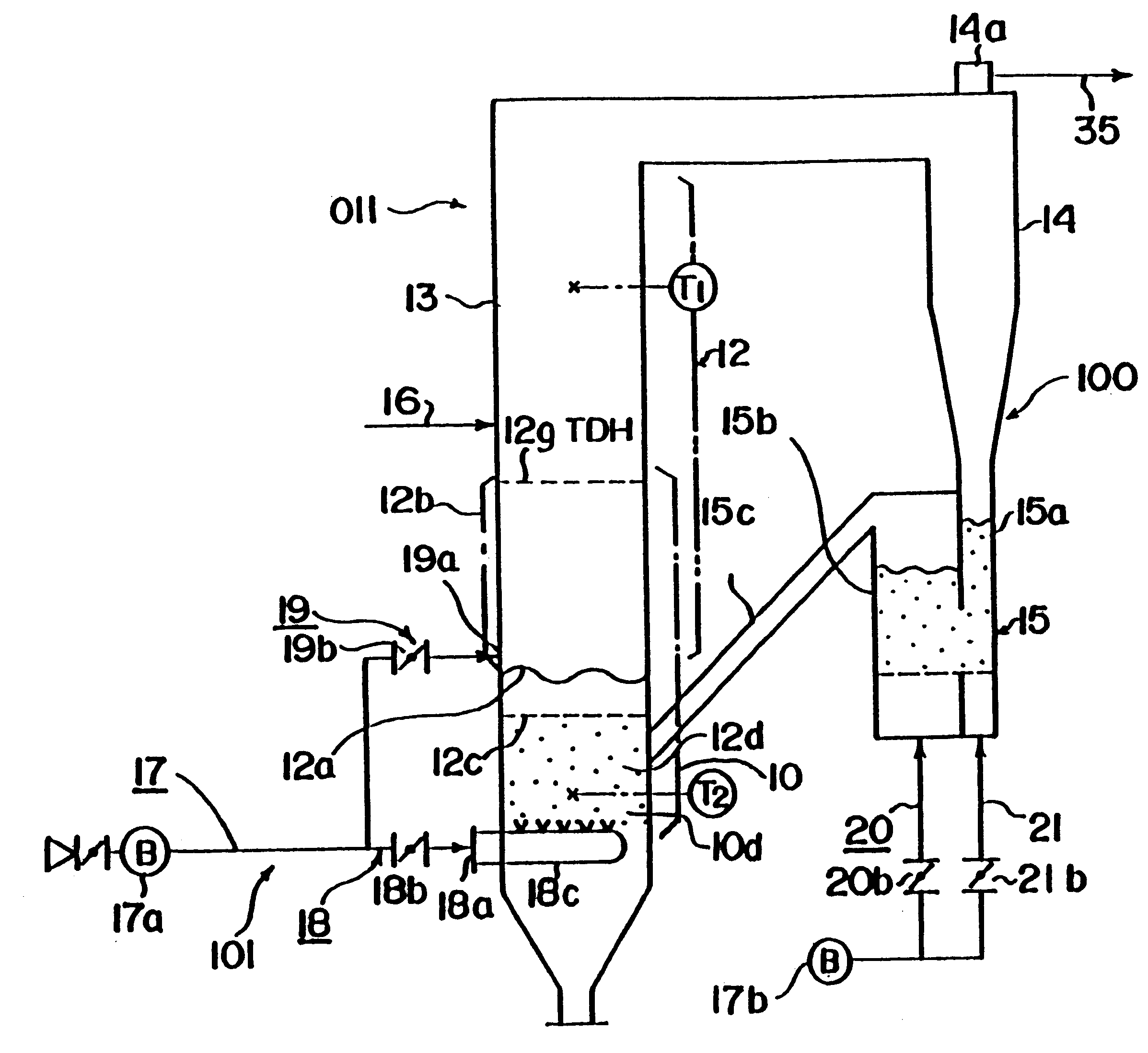
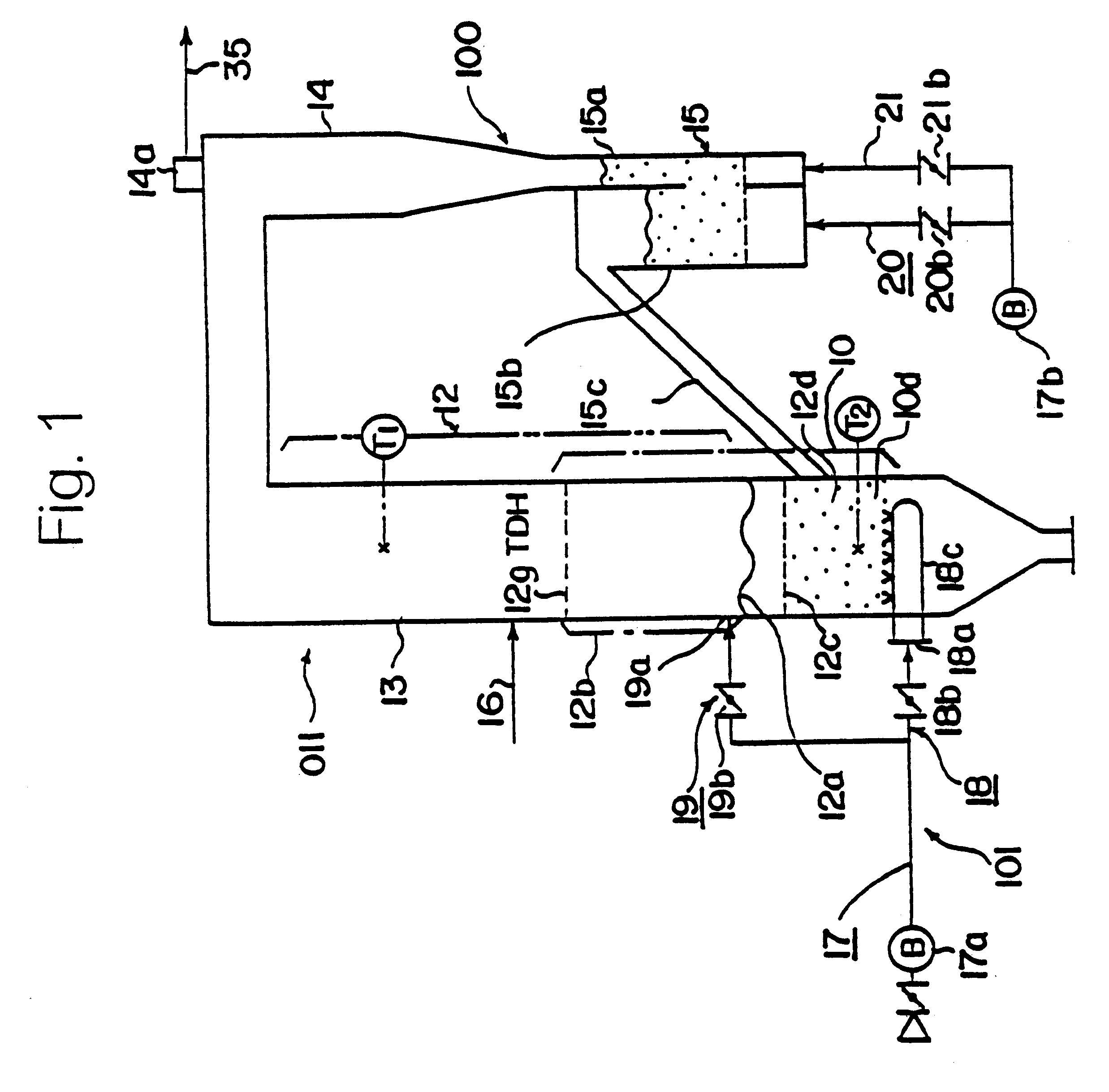
In FIG. 1, 011 is a fluidized bed incinerator. In the first embodiment, it is constructed as follows.

10 is the region in the lowest part of the tower which contains sand fluidized by air bubbles. Primary air 18 is injected into the bottom of this region via device 18c to disperse the fluidizing gas. Fluidizing sand 10d, the silica or other sand which serves as the fluidizing medium, is fluidized when air bubbles form in dense bed 12d.

12 is the region above the fluidizing region 10 in which the particles are entrained. When the bubbles on the surface 12a of the fluidized sand in the region 10 burst, particles are propelled upward into splash zone 12b. Secondary air 19 is introduced into splash zone 12b via aperture 19a, and the particles are entrained and conveyed upward into freeboard 13.

100 is the recirculation unit connected to the outlet of the aforesaid entraining region 12. The fluidizing medium which is driven up into splash zone 12b by the aforesaid secondary air 19 is entrai...

second preferred embodiment

In FIGS. 3 and 4, 011 is a fluidized bed incinerator. The second preferred embodiment of this invention has the following configuration. The said fluidized bed incinerator 011 consists of: a fluidizing region 10, in which primary air 18 is blown into the bed containing sand 10d, the fluidizing medium consisting of silica or the like, through gas dispersion device 18c, which is located on the bottom of the tower, in order to fluidize the sand; an entraining area 12, into which secondary air 25 is introduced, to entrain and convey the aforesaid sand 10d into the freeboard 13 above it, from any of channels 22, 23 or 24 through 1 or more, as selected by control unit 30, of inlets 22a, 23a or 24a, provided at three heights on the wall of the tower in splash zone 12b, into which sand 10d is carried when bubbles on surface 12a of the said fluidized bed 10 burst; recirculation unit 100, which entrains and conveys the aforesaid sand 10d which has been flung into splash zone 12b, on air intro...

third preferred embodiment

In FIG. 9, 011 is a fluidized bed incinerator which is the third preferred embodiment of this invention. This incinerator has the following configuration.

The said fluidized bed incinerator 011 has the following components. Fluidizing region 10 contains a mass of sand 10d, consisting of silica or some similar substance to serve as the fluidizing medium. Region 10 has a dense bed 11 on which static bed 12c is formed. Primary air 18 is blown into dense bed 11. The interior of the said dense bed 11 is fluidized by air bubbles and forms fluid surface 12a. As the bubbles burst, the particles of sand are thrust upward to form splash zone 12b. Secondary air 19, which entrains and conveys the grains of sand to the aforesaid splash zone, is admitted to the furnace and conveys the particles which serve as the fluidizing medium into freeboard 13, located above the fluidizing region.

The said fluidized bed incinerator 011 also has a separator 14, a cyclone or other device which conveys the afores...


PUM


Abstract

The objective of the present invention is to provide a fluidized bed incinerator which will increase the thermal capacity of the freeboard to respond to fluctuations of the load imposed by waste matter such as sludge or garbage with a high moisture content; which would absorb local and momentary temperature spikes due to load fluctuations or variations in the characteristics of the waste material. This invention comprises the steps of 1) injecting the primary air for fluidizing the fluidizing medium from a bottom of the fluidizing region; 2) injecting the secondary air into the splash region in which the bubbles on the surface of the fluidized sand blast and the particles are propelling upward when the bubbles are burst; 3) entraining and conveying upward the fluidizing medium to out of said incinerator via the freeboard; 3) recirculating the fluidizing medium to the fluidizing region; and 4) controlling the thermal capacity of the freeboard, and the temperature of the fluidizing medium to be constant by controlling the ration of the primary and secondary air.

Description

This invention concerns a method to operate a fluidized bed incinerator which incinerates waste containing solid carbon, such as sewage sludge, municipal garbage or industrial waste, and the incinerator employing this method. More specifically, it concerns a method to operate a fluidized bed incinerator which incinerates waste with a high moisture content, such as sewage sludge, and the incinerator employing this method.TECHNICAL BACKGROUNDFluidized bed incinerators can be divided into two types: those using fluidized beds of air bubbles, which are commonly employed to incinerate garbage and evaporated sewage sludge, and those using circulating fluidized beds, which are commonly employed in coal-burning boilers which generate electrical power and incinerators which burn a mixture of waste and fuel.Fluidized bed incinerators employing air bubbles work as follows. When the velocity of the gas exceeds the speed at which the particles comprising the medium of flow become a fluid, air bu...

Claims


Application Information

Patent Timeline
IPC IPC(8): F23G5/50F23C10/28F23C10/00F23G5/30
CPCF23C10/28F23G5/30F23G5/50F23G2203/501F23G2209/12
Inventor SHIMIZU, YOSHIHITOHONDA, HIROKITAKUMA, MASAOGODA, TOSHIHISASASATANI, SHIRO
Owner MITSUBISHI HEAVY IND LTD
Features
  • Generate Ideas
  • Intellectual Property
  • Life Sciences
  • Materials
  • Tech Scout
  • Unparalleled Data Quality
  • Higher Quality Content
  • 60% Fewer Hallucinations
Learn More