

Organic electroluminescent element
a technology of electroluminescent elements and organic materials, applied in the direction of discharge tube luminescnet screens, natural mineral layered products, transportation and packaging, etc., can solve the problems of poor stability, storage stability and stability, and the stability of charge-transporting materials, etc., to achieve the effect of increasing luminescent intensity and stable characteristics
- Summary
- Abstract
- Description
- Claims
- Application Information
AI Technical Summary
Benefits of technology
Problems solved by technology
Method used
Image

Examples
example 2
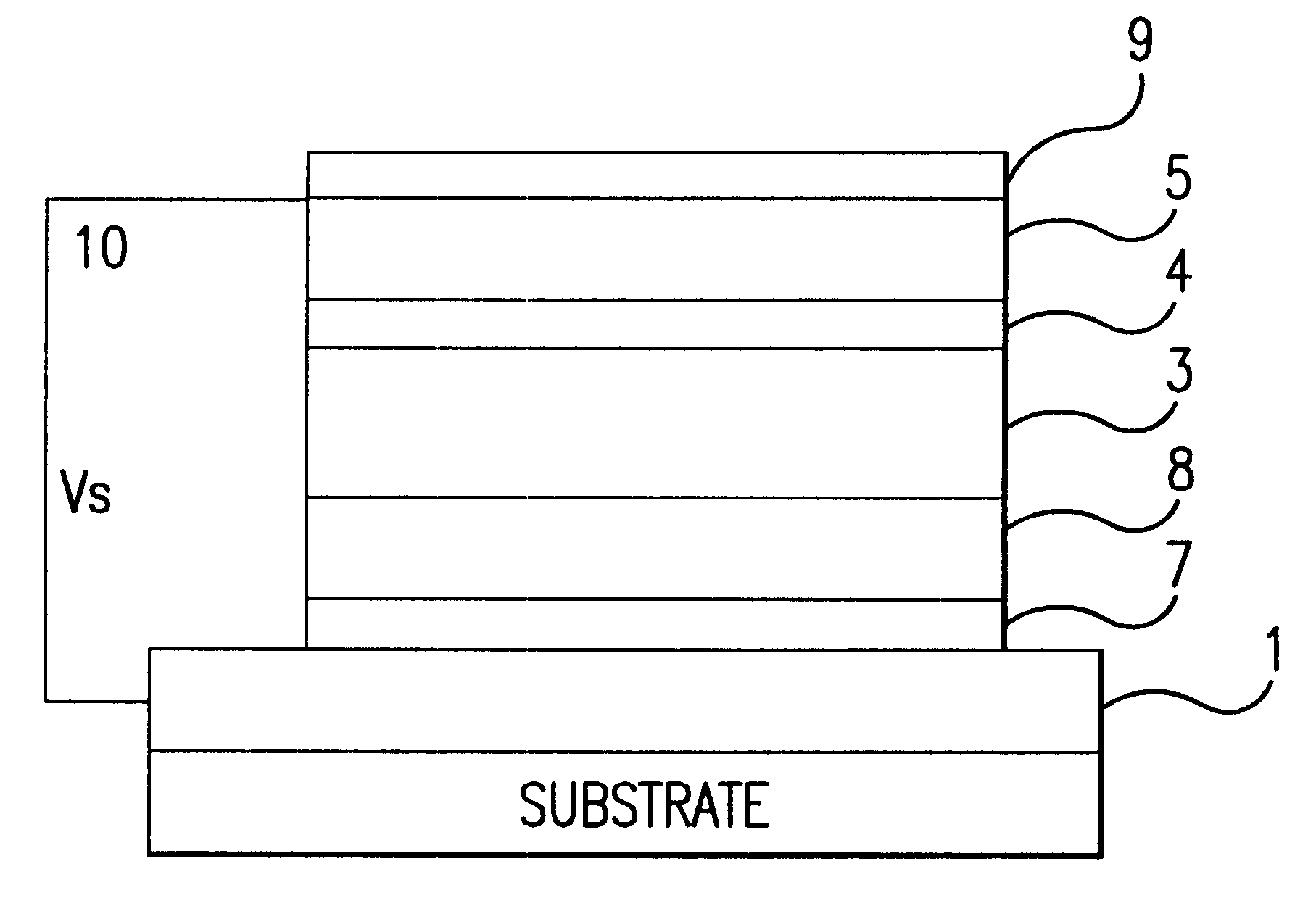
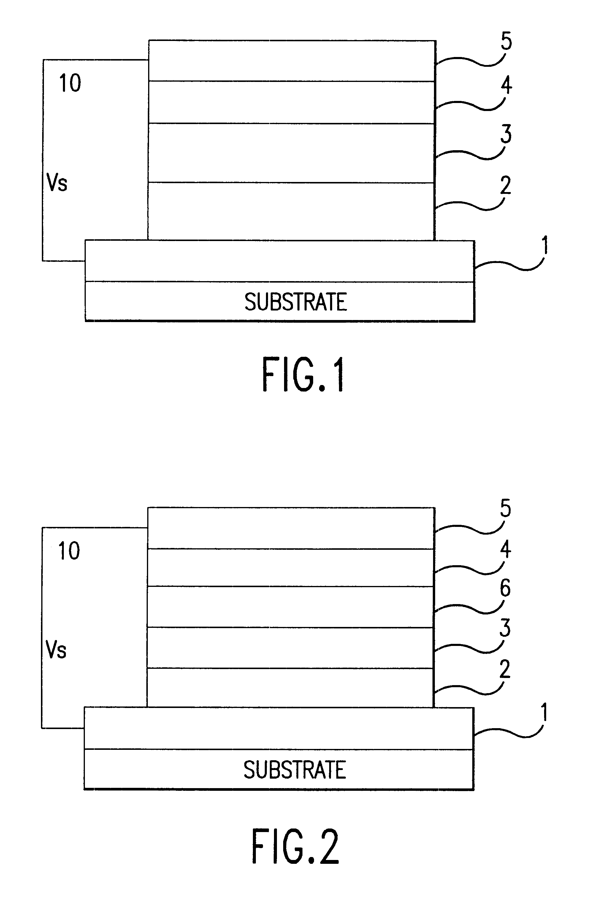
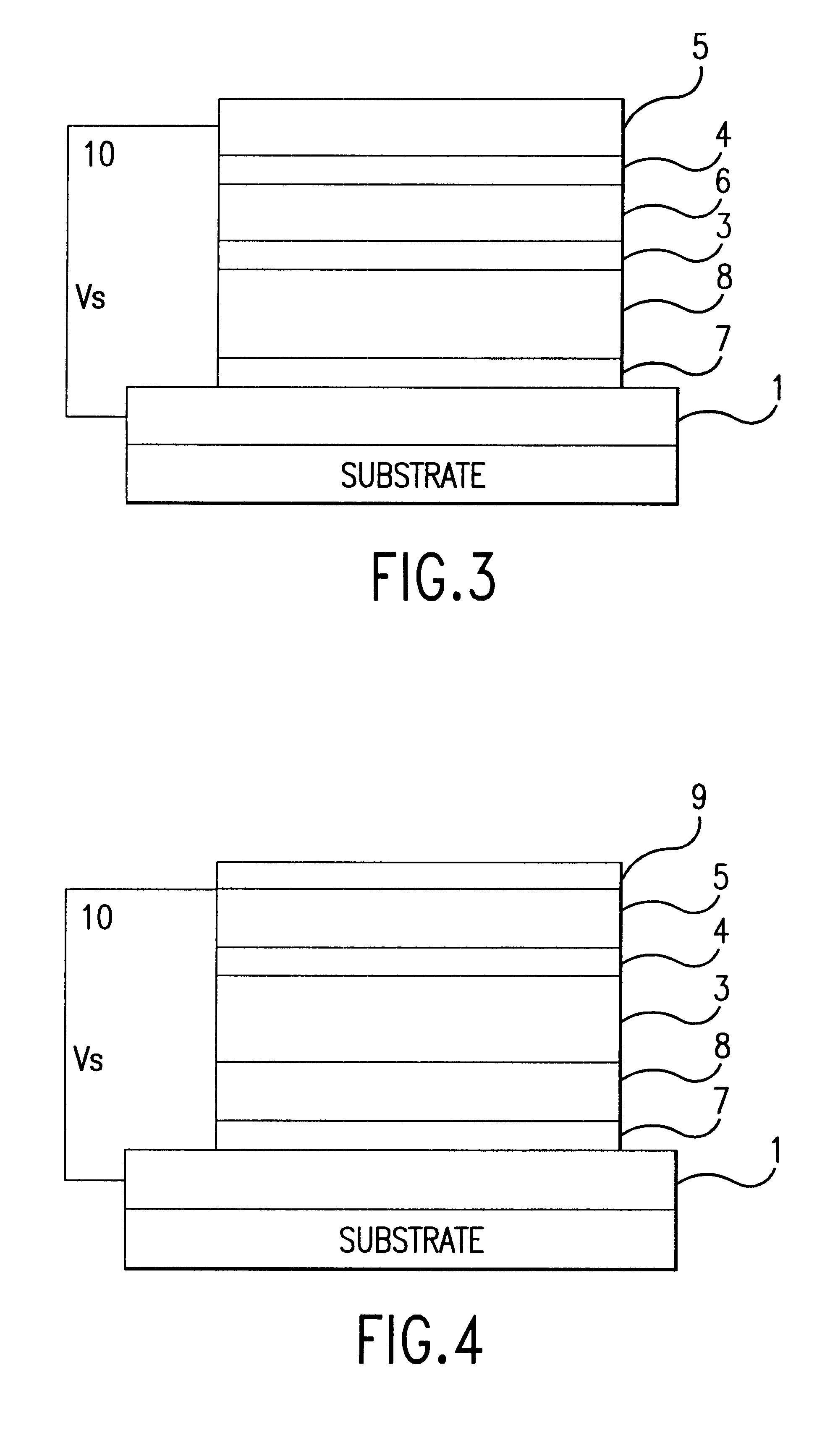
A thin hole injecting / transporting layer was formed on a glass substrate coated with indium-tin oxide via vacuum deposition using N,N'-diphenyl-N,N'-bis(3-methylphenyl)-1,1'-diphenyl-4,4'-diamine to form a layer 60 nm in thickness.
A thin layer of aluminum trisoxine 60 nm in thickness was superimposed over the aforesaid hole injecting / transporting layer via vacuum deposition to form an organic luminescing layer.
Then, magnesium and silver were co-deposited via vacuum deposition to form a thin layer 50 nm in thickness with an atomic ratio of 10:1 to form a negative electrode. A thin layer of magnesium and silver about 100 nm in thickness was then co-deposited over the aforesaid layer via resistance heating at an atomic ratio of 1:5.
The organic electroluminescent element was produced in this manner.
The magnesium used has a work function of 3.66 eV.
The silver used had a work function of 4.26 eV.
example 3
A thin hole injecting / transporting layer was formed on a glass substrate coated with indium-tin oxide via vacuum deposition using N,N'-diphenyl-N,N'-bis(3-methylphenyl)-1,1'-diphenyl-4,4'-diamine to form a layer 60 nm in thickness.
A thin layer of aluminum trisoxine 60 nm in thickness was superimposed over the aforesaid hole injecting / transporting layer via vacuum deposition to form an organic luminescing layer.
Then, magnesium and indium were vacuum deposited together to form a thin layer 60 nm in thickness with an atomic ratio of 10:1 to form a negative electrode. A thin layer of magnesium and indium about 140 nm in thickness was then co-deposited over the aforesaid layer via resistance heating at an atomic ratio of 1:5.
The organic electroluminescent element was produced in this manner.
The magnesium used has a work function of 3.66 eV.
The indium used had a work function of 4.09 eV.
reference example 1
An organic electroluminescent element was prepared in the same manner as in Example 1 with the exception that the negative electrode was formed by co-depositing magnesium and silver via resistance heating at an atomic ratio of 10:1 and layer thickness of 100 nm.
The magnesium used has a work function of 3.66 eV.
The silver used had a work function of 4.26 eV.
PUM
| Property | Measurement | Unit |
|---|---|---|
| thickness | aaaaa | aaaaa |
| thickness | aaaaa | aaaaa |
| thickness | aaaaa | aaaaa |
Abstract
Description
Claims
Application Information