Method for heat-treating metallic workpieces

a technology of heat treatment and workpieces, applied in the direction of furnace types, coatings, lighting and heating apparatuses, etc., can solve the problems of network interruption, high cooling gas pressure, complicated safety measures, etc., and achieve the effect of improving the quenching

Inactive Publication Date: 2002-08-06
IPSEN INT
View PDF7 Cites 12 Cited by
  • Summary
  • Abstract
  • Description
  • Claims
  • Application Information

AI Technical Summary

Benefits of technology

is to develop a method for heat-treating metallic workpieces in such a way that an improved quenching effect can be achieved in a simple and inexpensive fashion.

Problems solved by technology

However, high cooling gas pressures require complicated safety measures, with the time required for flooding or evacuating the vacuum furnace also being relatively long.
Another disadvantage that occurs during high-pressure gas quenching can be seen in the fact that the fan used for generating the flow of cooling gas in the vacuum furnace requires a comparatively high shaft output so as to ensure the required cooling gas speed for the load moments occurring at high pressures.
High currents of this type frequently result in network interruptions and high wear, primarily at the connecting points.
However, such starting devices are associated with higher costs and consequently not considered satisfactory with respect to economic considerations.
Since the fan can only be started once the minimum pressure during the flooding of the vacuum furnace with a cooling gas is reached, the quenching time and consequently the attainable quenching effect are disadvantageously influenced due to the unavoidable starting time of the fan.
Although the lower supply voltage also reduces the motor power, the motor power suffices for starting the fan due to the low pressure in the vacuum furnace and the low density of the cooling gas associated therewith.

Method used


Image

  • Method for heat-treating metallic workpieces
  • Method for heat-treating metallic workpieces
  • Method for heat-treating metallic workpieces

Examples


Embodiment Construction

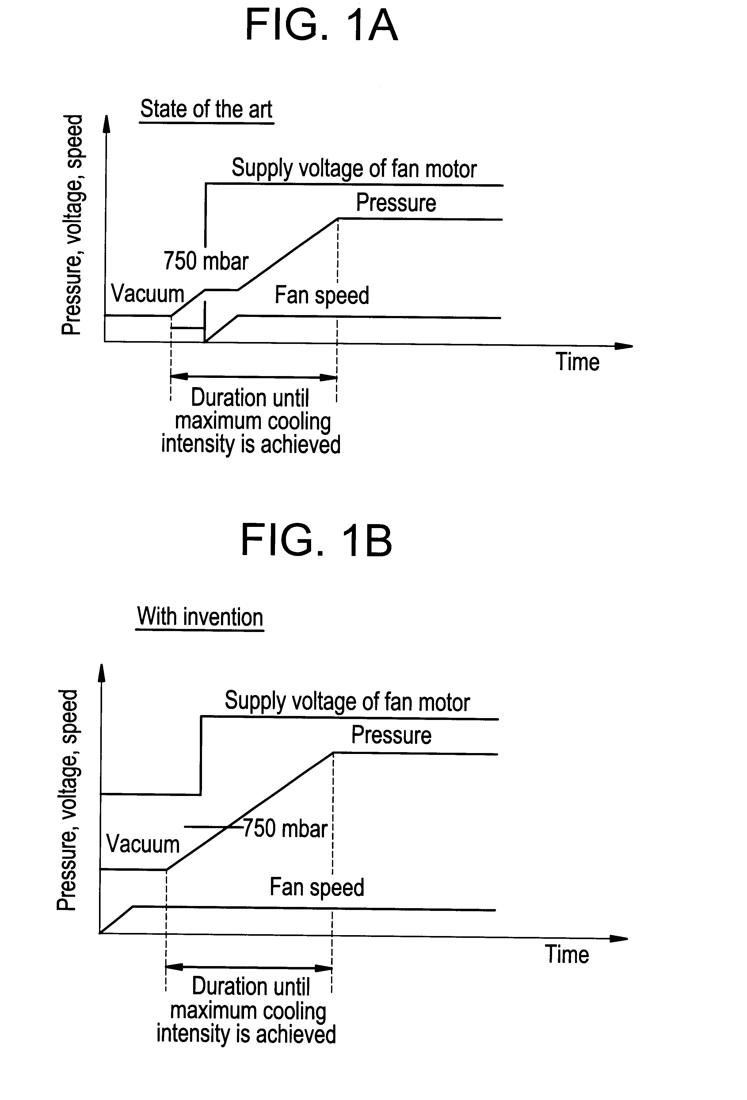
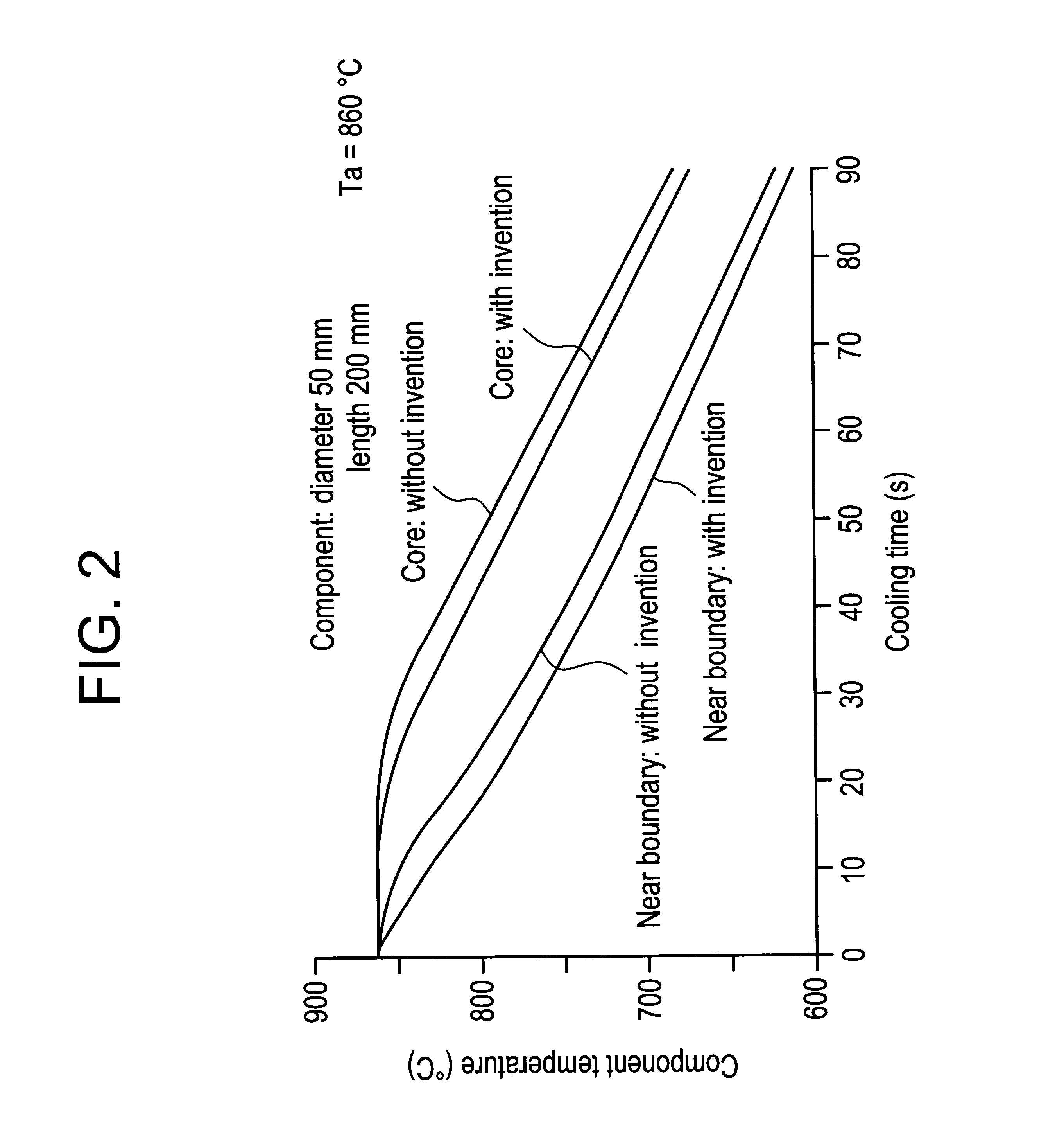
Details and additional advantages of the object of the present invention result from the following exemplary description of a method for case-hardening metallic workpieces.

The case-hardening process serves for providing the boundary layer of metallic workpieces with a significantly higher hardness, i.e., for providing the entire workpiece with superior mechanical properties. For this purpose, the boundary layer is initially enriched with carbon and / or nitrogen depending on the required characteristics of use and subsequently quenched to room temperature or below from an appropriate hardening temperature. An acceptable case-hardening with respect to the procedural technology can be achieved if the carbonizing or carbonitriding as well as the subsequent hardening are carried out in a vacuum furnace that allows a simple exchange of gaseous heat treatment mediums.

After the workpieces to be treated are, for example, carbonized in the vacuum furnace, the hardening process can be included ...


PUM

PropertyMeasurementUnit
supply voltageaaaaaaaaaa
pressureaaaaaaaaaa

Abstract

A method for heat-treating metallic workpieces, in which a flow of cooling gas is generated in a vacuum furnace by a fan in order to quench the workpieces, with the fan being driven by a rotary current motor that is operated with a predetermined supply voltage above a minimum pressure in the vacuum furnace which is determined with regard to the motor power of the rotary current motor. In order to additionally develop this method such that a simple and inexpensive improvement of the quenching effect is achieved, the fan is started at a pressure in the vacuum furnace which is lower than the minimum pressure, with the rotary current motor being operated with a second, lower supply voltage until the minimum pressure in the vacuum furnace is reached.

Description

INTRODUCTION AND BACKGROUNDThe present invention pertains to a method for heat-treating metallic workpieces, in which a flow of cooling gas is generated in a vacuum furnace by a fan in order to quench the workpieces, with the fan being driven by a rotary current motor that is operated with a predetermined supply voltage above a minimum pressure in the vacuum furnace, which pressure is determined with regard to the motor power of the rotary current motor.In the heat treatment of metallic workpieces, e.g., hardening, tempering or annealing, vacuum furnaces are increasingly utilized. The workpieces are cooled in these vacuum furnaces by a gaseous medium, e.g., nitrogen, after being heated. In comparison to conventional oil bath quenching or salt bath quenching methods, such a gas quenching provides the advantage that no contamination of the workpieces occurs, i.e., costly cleaning measures are eliminated. In order to achieve cooling effects similar to those of the oil bath quenching or...

Claims


Application Information

Patent Timeline
Patent Type & Authority Patents(United States)
IPC IPC(8): C21D1/74C21D1/767C21D9/00C21D1/773C21D1/613C21D1/56C21D1/18C21D1/00
CPCC21D1/767C21D9/0006C21D1/613C21D1/773
Inventor LEMKEN, KARL-HEINZ
Owner IPSEN INT
Why Eureka
Try Eureka