
Pollution control device

a technology of pollution control and control device, which is applied in the direction of dispersed particle separation, energy-based chemical/physical/physicochemical processes, and separation processes, etc., can solve the problems of reducing the efficiency of the devi

Inactive Publication Date: 2002-08-13
PIONEER INDAL TECH
View PDF65 Cites 23 Cited by
  • Summary
  • Abstract
  • Description
  • Claims
  • Application Information

AI Technical Summary

Problems solved by technology

Today's industrial processes create enormous amounts of pollutants.
Unfortunately, processes such as the one disclosed in Taylor do not complete the processing of dissociated contaminants, such as dissociated oxides.
Contaminants accumulate on the electrode and reduce the efficiency of the device.
Also, the cooling of the effluent gas may cause the effluent gas to reach several dew points within the pollution control device.
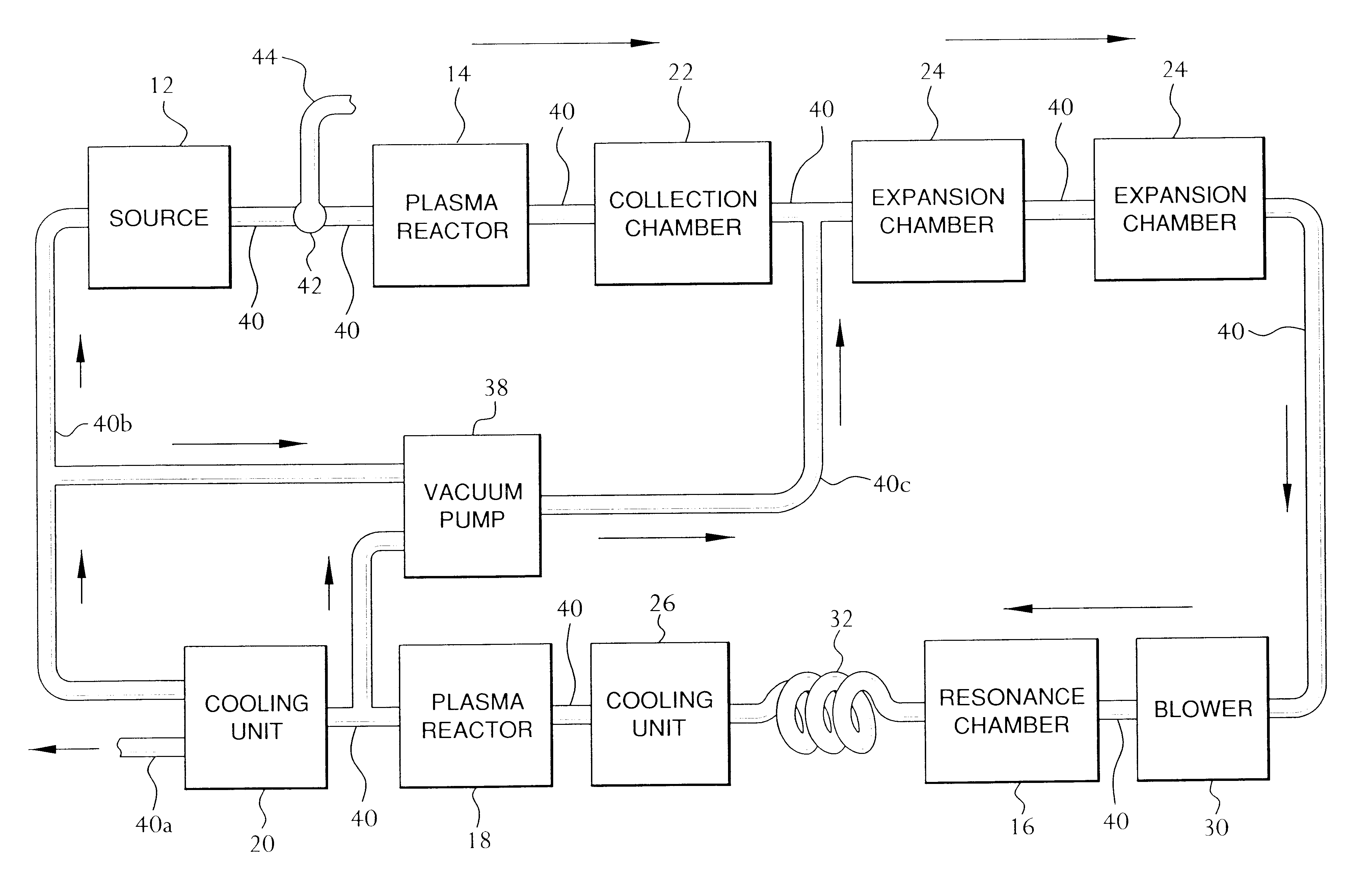
If the effluent gas prematurely reaches dew points while passing through the pollution control device, unwanted clogging of the components and piping 40 of the apparatus may occur.
These build-ups impede the operation of prior art non-thermal plasma reactors, reduce their efficiency, and give rise to the need to replace the inner conductors, such as corona wires, of the these prior art non-thermal plasma reactors.

Method used


Image

  • Pollution control device
  • Pollution control device
  • Pollution control device

Examples


example ii

In a second example, a test was conducted by an independent lab that performs emission certification testing in accordance with EPA methods. The exhaust of a 40 horse power diesel generator was coupled to the pollution control device described above.

The results indicated a reduction in flow rate from 241 ACFM (actual cubic feet per minute) to 155 ACFM, O.sub.2 as a percentage of the total effluent emission stream increased after the process, a reduced CO.sub.2 percentage level from 2.15% to 1.04% of the effluent volume, a reduced CO level from 286 ppmV to 156 ppmV and 0.29 lb / hr to 0.10 lb / hr (65.5%), and a reduced NO.sub.x levels from 238 ppmV to 78 ppmV and 0.40 lb / hr to 0.09 lb / hr (77.5%). SO.sub.x levels changes were negligible due to the trace amounts of sulfur in the diesel fuel.

example iii

In a third example, the exhaust of a forty horse power diesel generator was coupled to the pollution control device described above. A test was performed in house using standard testing techniques. The aforementioned blower included a variable speed fan and was used to insure the CFM velocity of the effluent gas through the pollution control device equaled the base-line CFM of the untreated emissions.

The results indicated slight increases in O.sub.2 percentage levels, a 50% decrease in CO.sub.2 percentage levels from 2% to 1% of the effluent volume, a 64% decrease in CO levels from 278 ppmV to 100 ppmV, a 28% decrease in SO.sub.2 levels from 464 ppmV to 332 ppmV, a 72% decrease in NO levels from 170 ppmV to 48 ppmV, and an 86% decrease in NO.sub.x levels from 150 ppmV to 20 ppmV.

example iv

In a fourth example, a test was conducted by an independent lab that performs emission certification testing in accordance with EPA methods. The exhaust of a coal-fired incinerator was coupled to the pollution control device described above. The aforementioned blower included a variable speed fan and was used to insure the CFM velocity of the effluent gas through the pollution control device equaled the base-line CFM of the untreated emissions.

The NO.sub.x and SO.sub.x levels were monitored. The results indicated reductions in SO.sub.2 levels from 205 ppmV to 51 ppmV and 0.19 lb / hr to 0.06 lb / hr (68.4%), and reduced NO.sub.x levels from 68 ppmV to 31 ppmV and 0.05 lb / hr to 0.02 lb / hr (60.0%).


PUM


Abstract

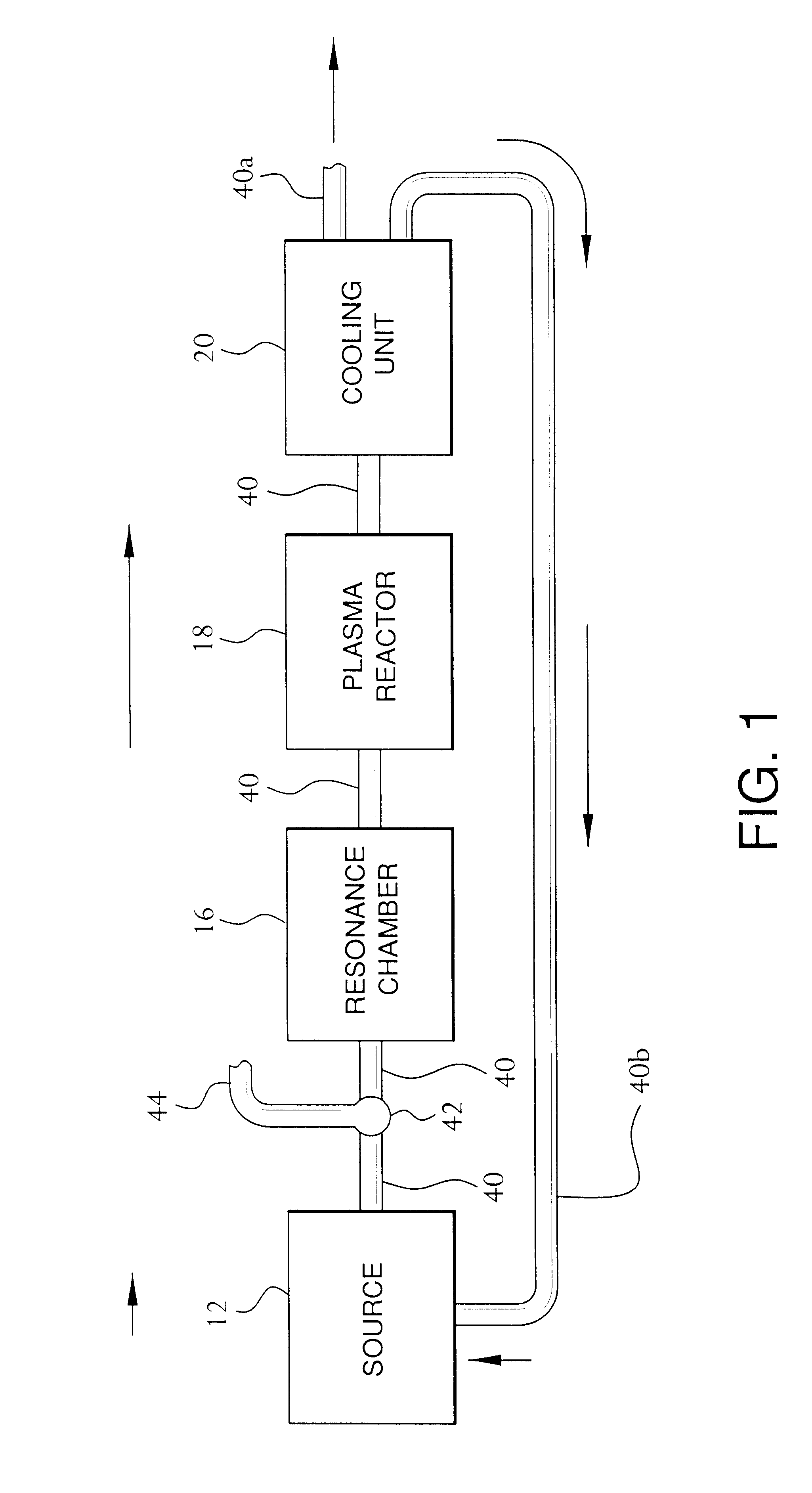
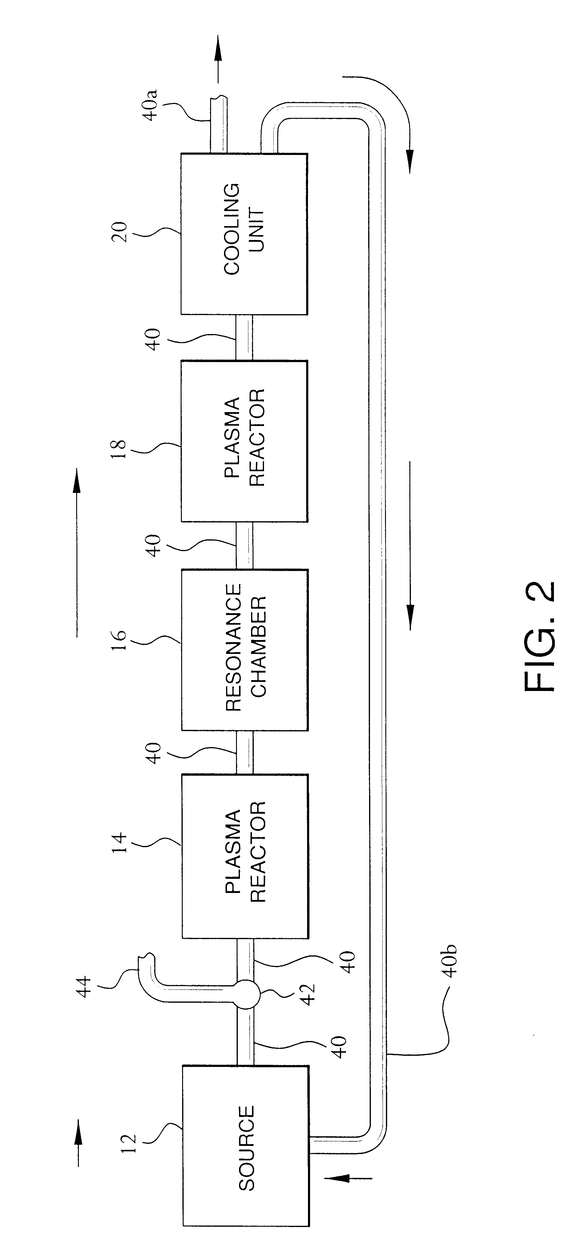
A pollution control apparatus and method reduces contaminants, such as NOx and SOx pollutants, from an effluent gas stream. The pollution control device includes a resonance chamber that ionizes the effluent gas stream. The contaminants of the effluent gas stream are destroyed in a non-thermal plasma reactor. The effluent gas is then cooled in a cooling unit to substantially place the effluent gas in a non-excited state prior to releasing the effluent gas into the environment or re-injecting the effluent gas into the source of the effluent gas. Re-association of the radical oxides into harmful pollutants is thereby substantially prevented.

Description

The present invention relates to pollution control apparatuses and methods for reducing contaminants in an effluent gas flow, and more particularly to pollution control devices utilizing non-thermal plasma reactors.DESCRIPTION OF THE RELATED ARTToday's industrial processes create enormous amounts of pollutants. Many of these sources release gases containing these pollutants into the environment. Examples of these sources include factories, combustion engines, dump sites, land fills, sewage treatment plants and lagoons and waste heaps, to name a few. The primary air pollutants in these gases include NO, NO.sub.2, SO.sub.2, CO.sub.2, and hydrocarbons.Several devices and methods for removing pollutants from these gases have developed. These devices utilize mechanical, electrical, electrochemical, and chemical processes. Typical examples include filters, aqueous scrubbers, electrostatic precipitators, and catalytic converters.Some existing electrical and electrochemical pollution contro...

Claims


Application Information

Patent Timeline
Patent Type & Authority Patents(United States)
IPC IPC(8): B01D53/32
CPCB01D53/32Y02C20/20
Inventor BIANCO, EDWARD DOMENICKLINE, MICHAEL A.
Owner PIONEER INDAL TECH
Learn More