Exhaust gas recirculation device and control method thereof

Inactive Publication Date: 2002-08-20
KOMATSU LTD
View PDF10 Cites 116 Cited by
  • Summary
  • Abstract
  • Description
  • Claims
  • Application Information

AI Technical Summary

Problems solved by technology

In the internal combustion engine employing exhaust gas recirculation, when differential pressure on the exhaust side and the intake side fluctuates, because flow rate of the exhaust gas flowing in the exhaust gas recirculation duct also fluctuates, the recirculation rate cannot be controlled at a constant level.
Accordingly, a predetermined amount of the exhaust gas does not recirculate to the intake side even when the recirculation amount is set in accordance with operation of the internal combustion engine, so that it is difficult to set an op

Method used


Image

  • Exhaust gas recirculation device and control method thereof
  • Exhaust gas recirculation device and control method thereof
  • Exhaust gas recirculation device and control method thereof

Examples


Embodiment Construction

)

An embodiment of the present invention will be described below with reference to attached drawings.

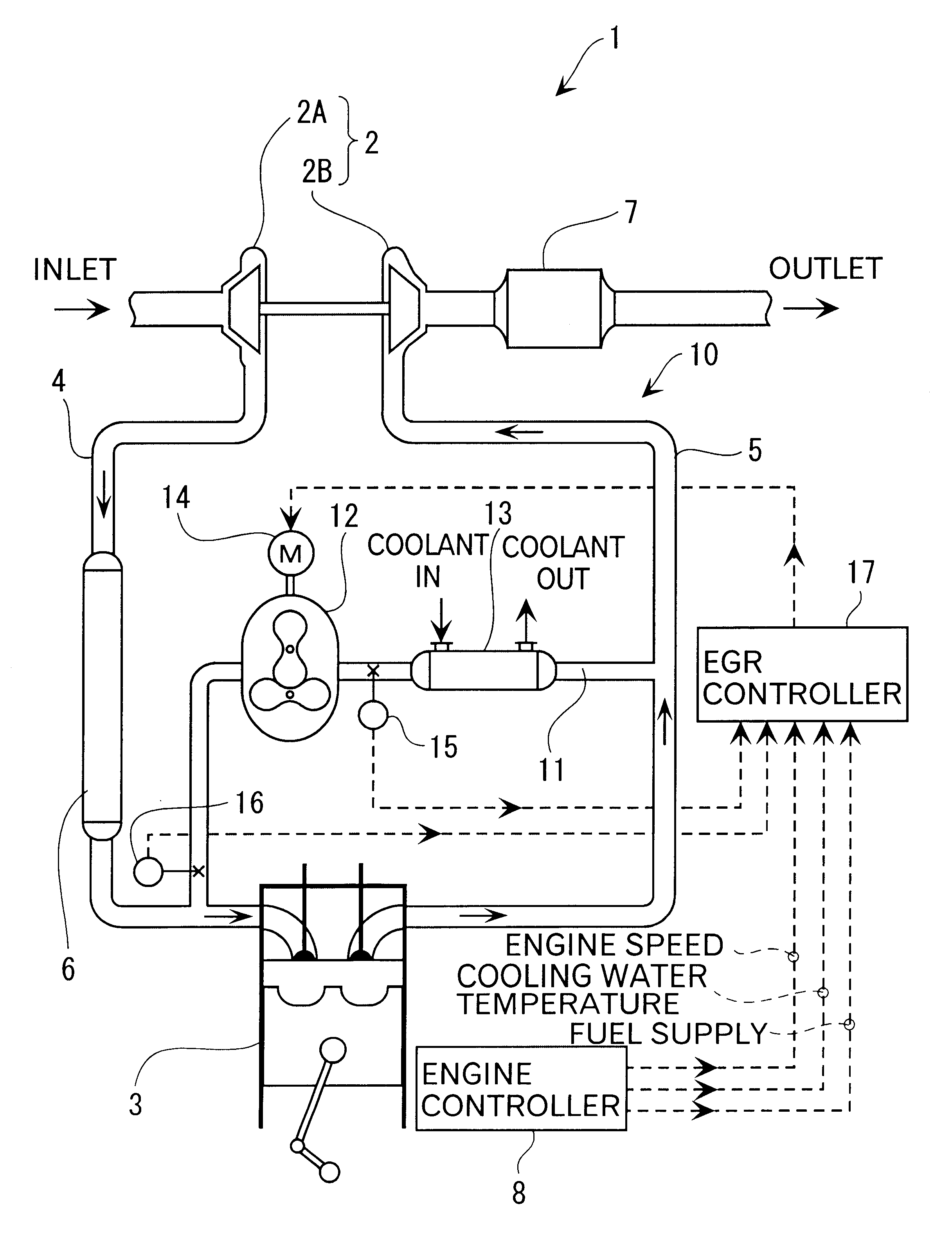
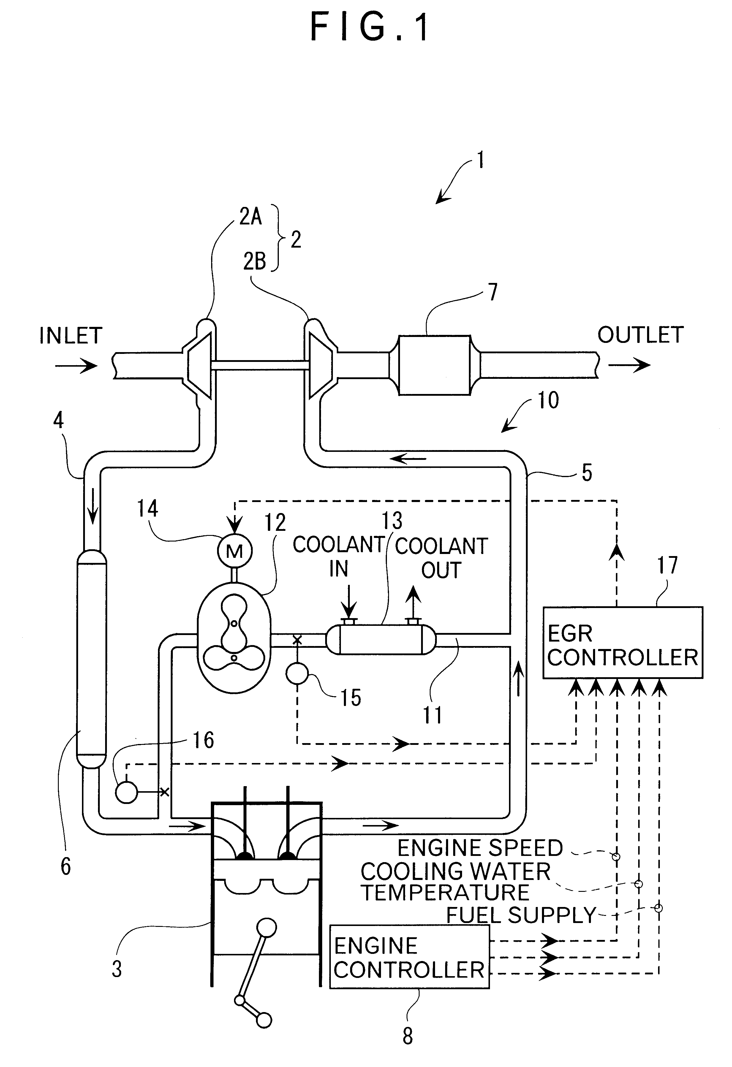
FIG. 1 shows a diesel engine 1 as an internal combustion engine according to first embodiment of the present invention. The diesel engine 1 has an exhaust gas recirculation device 10 for extracting a part of the exhaust gas to recirculate to intake side.

The diesel engine 1 conducts supercharging by a turbocharger 2 and has an intake duct 4 for introducing fresh air from the outside to a cylinder 3 and an exhaust duct 5 for discharging the exhaust gas from the cylinder 3 to the outside.

A centrifugal intake-air compressor 2A and an air-cooling inter cooler 6 for cooling the intake air compressed by the centrifugal intake-air compressor 2A is provided to the intake duct 4.

The exhaust duct has an exhaust gas turbine 2B for driving the centrifugal intake-air compressor 2A on the intake side and a catalyst 7 for cleaning the exhaust gas on downstream side of the exhaust gas turbine 2B.

The t...


PUM


Abstract

A Roots blower driven by a direct-current motor provided to a recirculation duct for connecting an exhaust duct and an intake duct to extract a part of exhaust gas of a diesel engine to recirculate to an intake side. Accordingly, even when a differential pressure between an exhaust side and the intake side, or even when a pressure on the intake side is higher than the exhaust side fluctuates, the exhaust gas flowing to the recirculation duct can be forcibly pumped by the Roots blower while appropriately controlling flow rate thereof, so that an optimum recirculation amount of exhaust gas in accordance with operation condition of the diesel engine can be recirculated to the intake side.

Description

1. Field of the InventionThe present invention relates to an exhaust gas recirculation device for removing nitrogen oxide from the exhaust gas of an internal combustion engine and control method thereof.2. Description of the Related ArtConventionally, exhaust gas recirculation (EGR) for returning a part of exhaust gas to intake side is used for reducing nitrogen oxide, so-called NOx, contained in the exhaust gas of an internal combustion engine, especially a reciprocating engine.According to the exhaust gas recirculation, a gas having a large thermal capacity, such as carbon dioxide and water vapor, is mixed into combustion air supplied to the internal combustion engine to increase thermal capacity of the air, so that maximum combustion temperature is lowered, thus decreasing the level of nitrogen oxide.An example of an internal combustion engine using the exhaust gas recirculation is shown in Japanese Utility Model Laid-Open Publication No. Hei 5-30454. According to the exhaust gas...

Claims


Application Information

Patent Timeline
IPC IPC(8): F02D21/00F02D21/08F02M25/07F02B3/06F02B3/00
CPCF02D21/08F02M25/0707F02M25/071F02M25/0731F02M25/0739F02M25/0742F02M25/0701F02B3/06F02M25/0738F02M25/0754Y02T10/121F02M26/07F02M26/05F02M26/50F02M26/28F02M26/33F02M26/34F02M26/36F02M26/47
Inventor SATO, FUMIHIDEKOMIYAMA, KUNIHIKOONODERA, YASUYUKIKANZAKI, YOSHIKI
Owner KOMATSU LTD
Why Eureka
Try Eureka