Oscillator and radio equipment
a technology of oscillator and radio equipment, applied in the direction of waveguides, waveguide type devices, multiple-port networks, etc., can solve the problems of increased loss, high cost, and inability to meet the needs of radio equipment,
- Summary
- Abstract
- Description
- Claims
- Application Information
AI Technical Summary
Benefits of technology
Problems solved by technology
Method used
Image
Examples
first embodiment
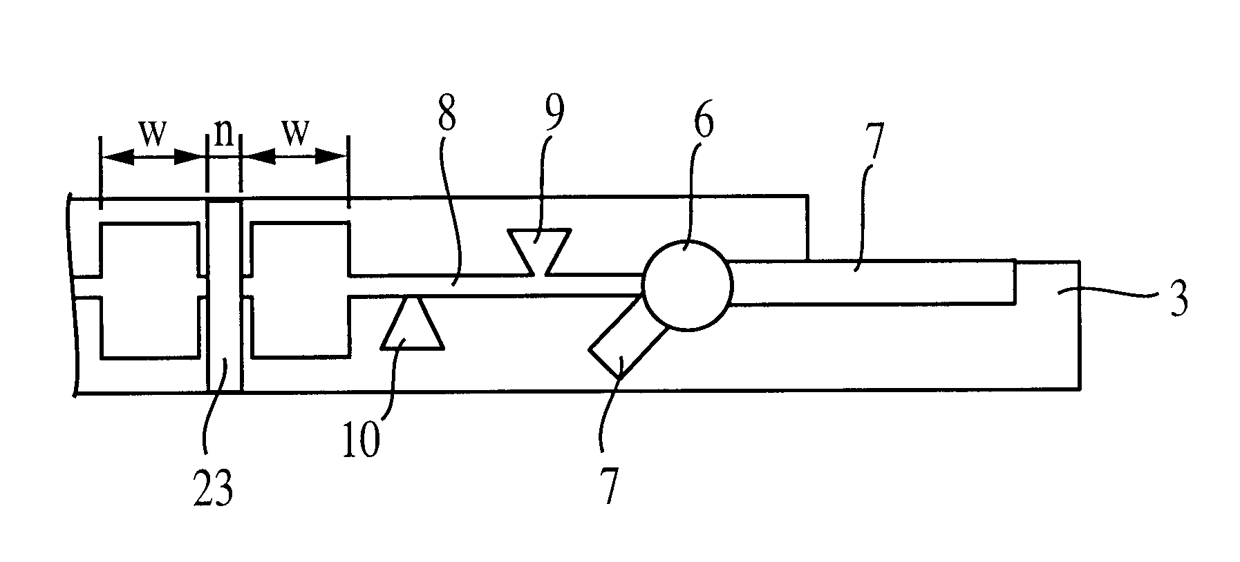
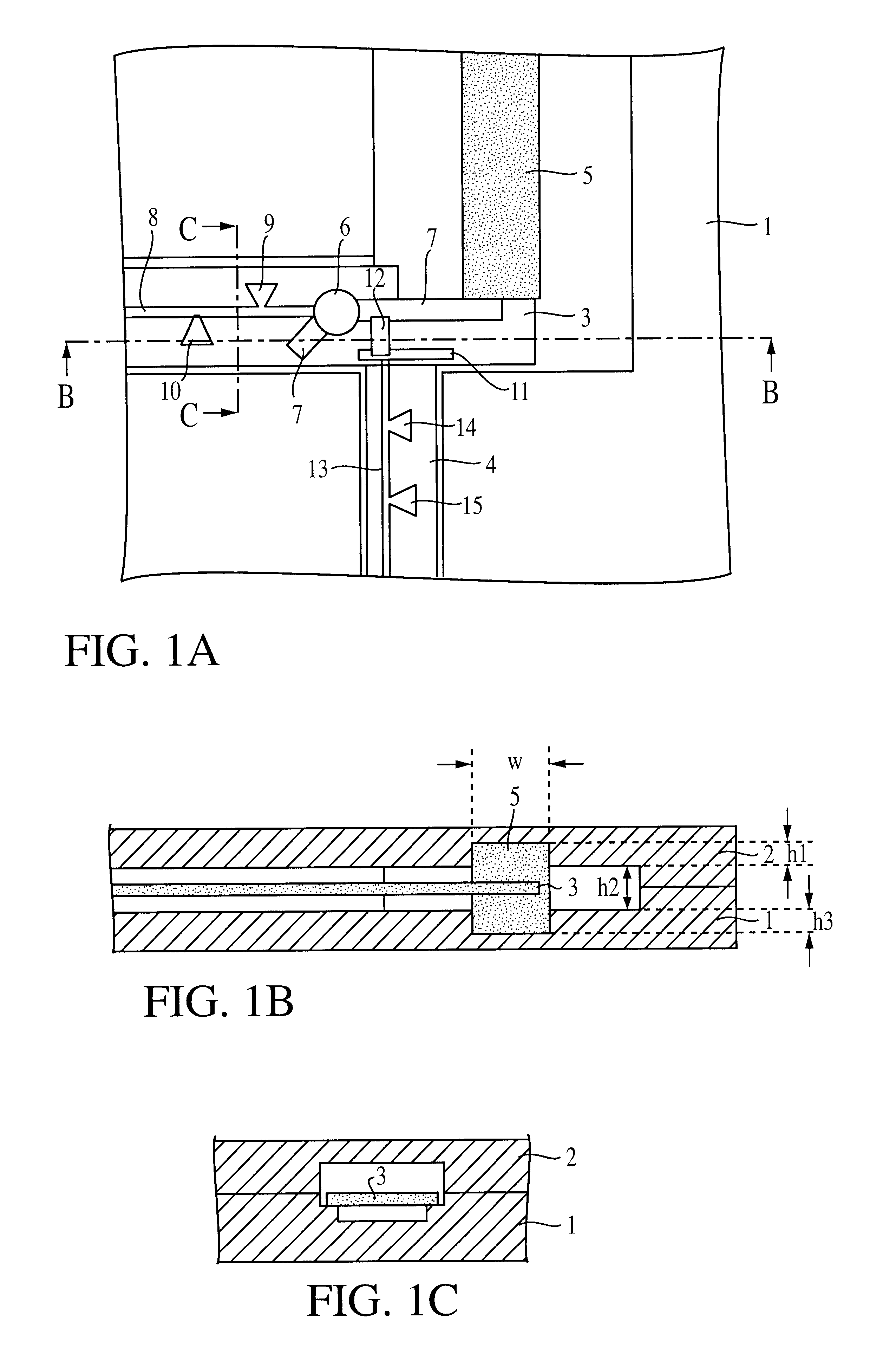
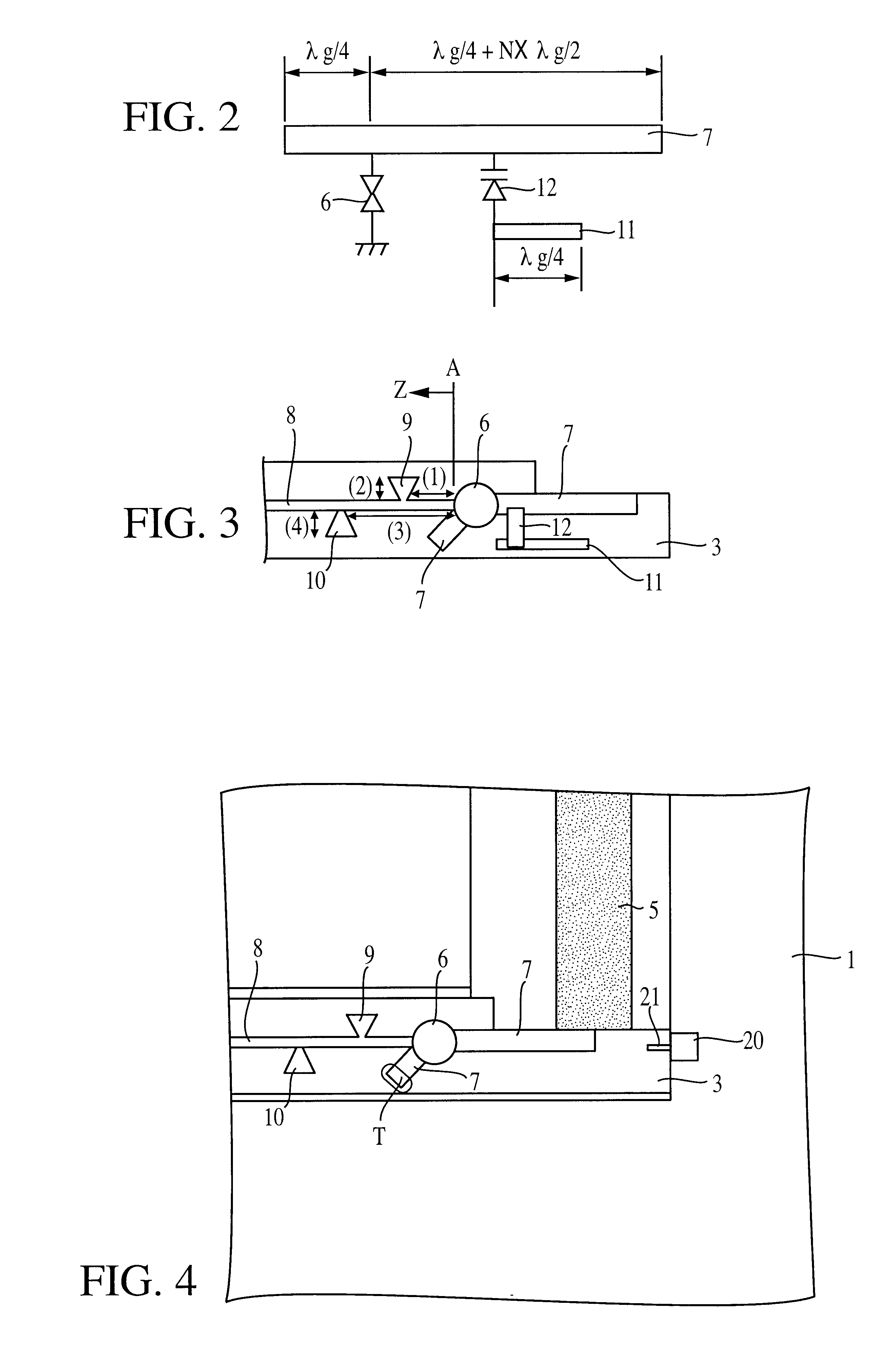
The construction of an oscillator in accordance with the present invention will be described with reference to FIGS. 1A through 3.
FIG. 1A is a plan view showing an oscillator having two (upper and lower) conductor plates, without showing the upper conductor plate. FIGS. 1B and 1C are cross-sectional views taken along the lines B--B and C--C, respectively. In FIGS. 1A-1C, reference numerals 1 and 2 denote a lower conductor plate and an upper conductor plate, respectively. These two conductor plates form an oscillator in the space sandwiched therebetween. Reference numerals 3 and 4 each denote dielectric substrates. A line 7 for the oscillation circuit is provided on the top surface of the dielectric substrate 3, and at a predetermined position thereof, a Gunn diode 6 is connected. The Gunn diode 6 is of a pill package type, and is mounted on the lower conductor plate 1. The protruded electrode of the Gunn diode is inserted through a hole formed in the dielectric substrate 3, and the ...
second embodiment
Next, the construction of an oscillator in accordance with the present invention is shown in FIG. 4. FIG. 4 is a plan view showing the oscillator in the state without the upper conductor plate. Unlike the example shown in FIGS. 1A-1C, an electrode 21 and an adjustment terminal 20 connected thereto are provided on the dielectric substrate 3. In this example, a structure for making frequency variable by voltage control is not provided.
In FIG. 4, the electrode 21 is weak-coupled with the line 7, and is arranged so as to monitor oscillation signals by connecting a spectrum analyzer or the like to the adjustment terminal 20. For example, when adjusting an oscillating frequency, trimming is performed with respect to one open end T portion of the line 7 so that the fundamental frequency thereof becomes a half value of the second harmonic frequency to be actually used.
Since the electrode 21 is, thus, merely weak-coupled with the line 7, it exerts no adverse effect. In addition, since the el...
third embodiment
Next, the construction of an oscillator in accordance with the present invention will be described with reference to FIG. 5.
In the first and second embodiments, the dielectric substrate 3 is disposed in the space sandwiched between the upper and lower conductor plates, but in this third embodiment, a dielectric substrate 3 is disposed on the outside of the upper and lower conductor plates. Specifically, a slot 22 is formed along the longitude of the dielectric strip 5 on the upper conductor plate 2, and the dielectric substrate 3 is disposed so that the line 7 of an oscillation circuit is orthogonal to the slot 22. The construction of this dielectric substrate 3 is basically the same as one shown in FIGS. 1A-1C or 4. However, the mode (TEM mode) of microstrip line propagating through the line 7 of the oscillating circuit, and the LSM mode of the dielectric line are magnetic-field coupled via the slot 22. Thus, the magnetic field of the TEM mode spreads via the slot 22, whereas that ...
PUM
 Abstract
Description
Claims
Application Information
 - R&D
- Intellectual Property
- Life Sciences
- Materials
- Tech Scout
- Unparalleled Data Quality
- Higher Quality Content
- 60% Fewer Hallucinations
Browse by: Latest US Patents, China's latest patents, Technical Efficacy Thesaurus, Application Domain, Technology Topic, Popular Technical Reports.
© 2025 PatSnap. All rights reserved.Legal|Privacy policy|Modern Slavery Act Transparency Statement|Sitemap|About US| Contact US: help@patsnap.com


