Circuit for providing a logical output signal in accordance with crossing points of differential signals

a technology of differential signal and output signal, which is applied in logic circuit coupling/interface arrangement, instruments, pulse technique, etc., can solve the problems of parasitic signal distortion, inability to reliably estimate the tested output signal, and inability to provide logical output signal in accordance with crossing points of differential signal, so as to achieve the effect of reducing the amount of current and not causing a negative impact on the bandwidth of the input channel of the a

Inactive Publication Date: 2002-09-10
ADVANTEST CORP
View PDF3 Cites 50 Cited by
  • Summary
  • Abstract
  • Description
  • Claims
  • Application Information

AI Technical Summary

Benefits of technology

The circuit structure of the invention thus allows that two single-ended comparators are combined to a differential comparator without adding parasitic components to the measurement node of an ATE to which it is connected and therefore without causing a negative impact on the bandwidth of the ATE's input channels. The number of additional components needed for the combining circuitry of the comparators as well as the additional current can also be minimal.

Problems solved by technology

Regarding the circuits which are supposed to receive DUT generated signals, a problem occurs if DUTs which have single-ended signals (signals which need only one pin for exit to the ATE) should be tested on the same testing equipment as DUTs which provide differential signals (signals which need two pins where one pin represents the normal logic output level and the other pin represents the complementary logic output level).
A major disadvantage of this concept is the timing inaccuracy that occurs when the zero crossing point of the signals SIG-NSIG is not at the same zero crossing point of (SIG-VTH) and / or (NSIG-VTH).
From this it is clear that further processing of inaccurate DUT signals by an ATE leads to measurement errors which in most cases can not result in a reliable estimation of the tested DUT.
The implementation of FIG. 4a suffers from the fact that there is an extra line required for the differential comparator output OUTD.
The approaches according to FIGS. 4a and 4b have significant disadvantages in that each incoming signal line is loaded by an additional comparator that is not used when single-ended applications are run by the ATE.
On the other hand, when the ATE is running differential applications the single-ended comparators C1 and C2 contribute to parasitic signal distortions.
This has a negative impact on the ATE performance, because any incoming signal is delayed and frequency-limited due to parasitic capacitances on the input lines of the comparators.
As a further disadvantage the fact can be regarded that the above-described approaches need considerably more electrical power and more silicon space for implementation.
Furthermore, the solution shown in FIG. 4c is not useful for high-speed applications, because signals transferred via switches become distorted per se and provide signal delays and other distortions by themselves.
Both solutions, however, again have severe disadvantages, like higher cost, extra floor space, and restrictions in universality of channel usage by the ATE.

Method used


Image

  • Circuit for providing a logical output signal in accordance with crossing points of differential signals
  • Circuit for providing a logical output signal in accordance with crossing points of differential signals
  • Circuit for providing a logical output signal in accordance with crossing points of differential signals

Examples


Embodiment Construction

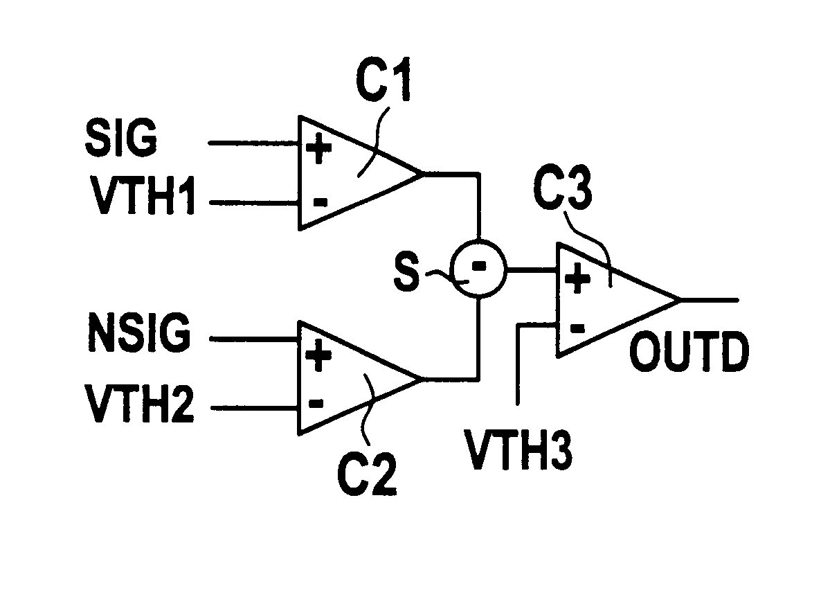
The new idea on which the invention is based takes advantage of the fact that almost all comparing circuits (or comparators) consist of more than one amplifier stage where the first stage due to its relative low amplification provides a significant wide linear region in its steady-state characteristic (characteristic curve).

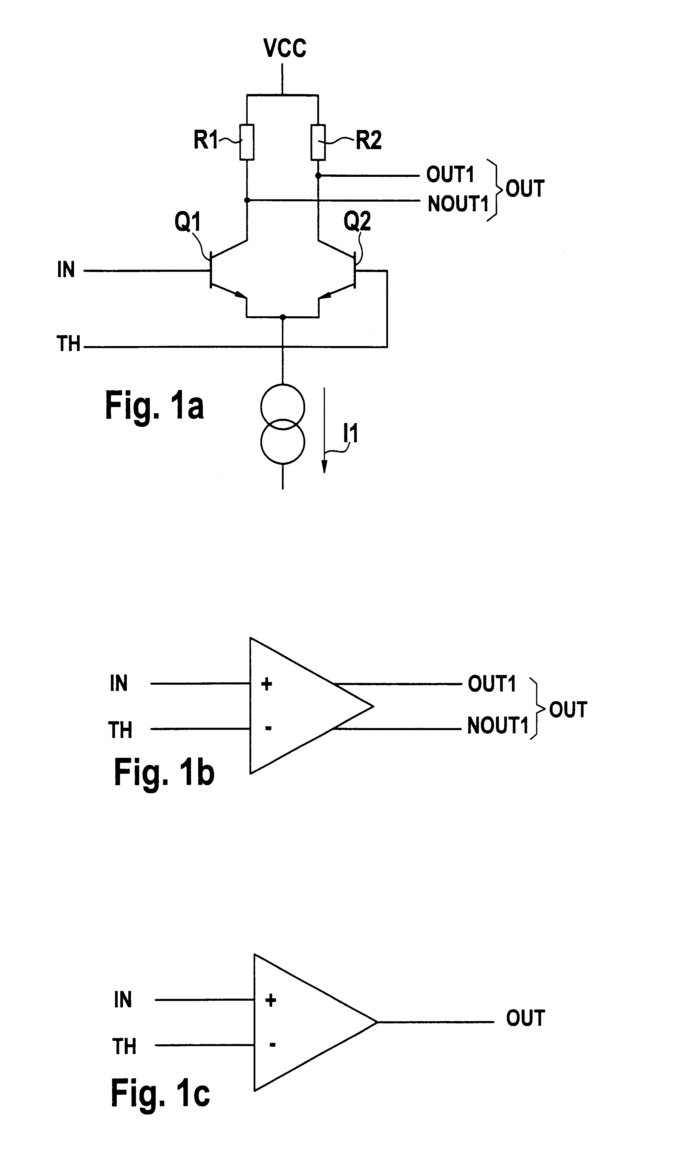
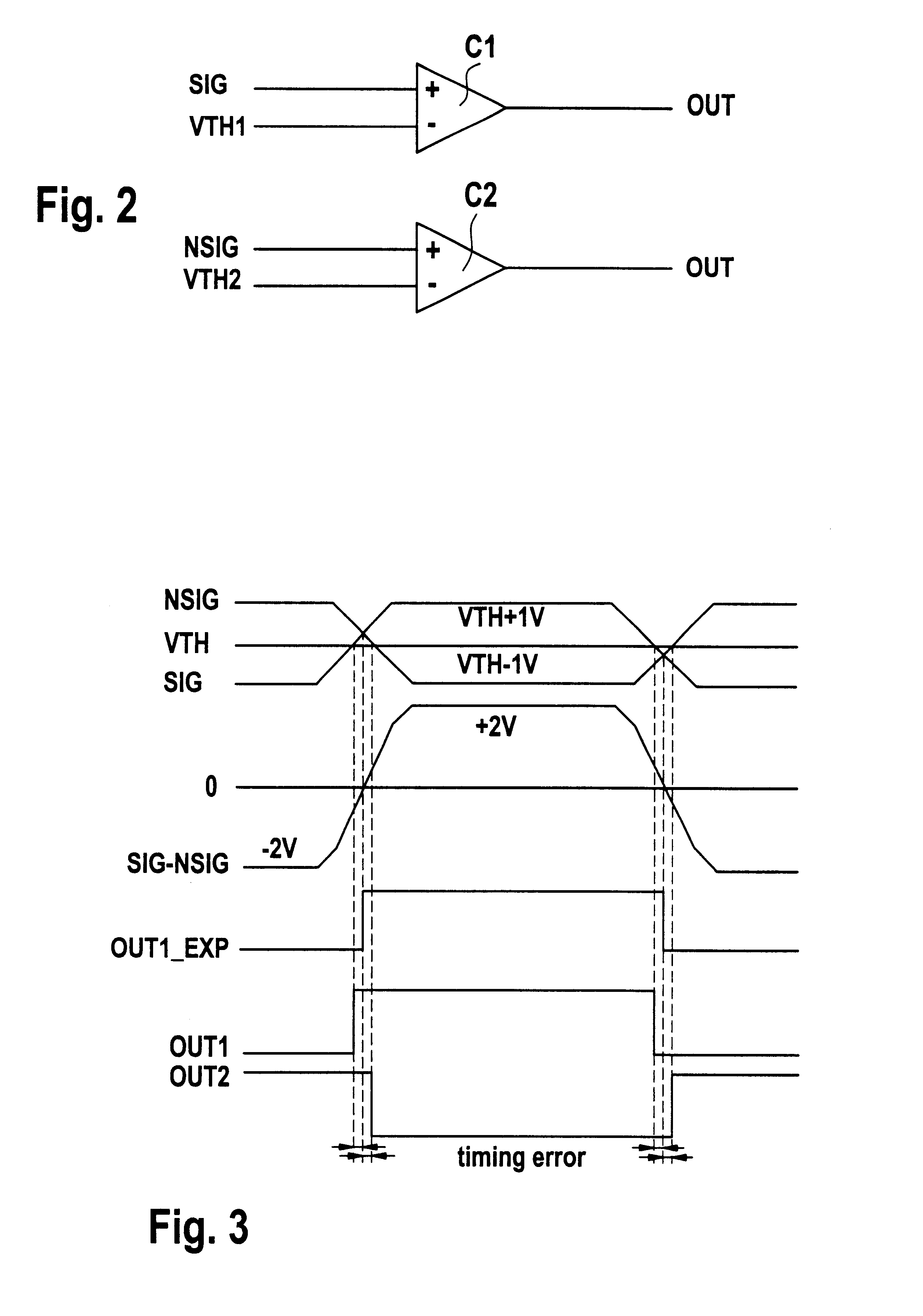
FIG. 5 shows the basics of the invention. Two amplifier stages CS1 and CS2 of a comparator, e.g. C1 of FIG. 2, are shown in FIG. 5. The same subdivision into at least two stages of the amplifier stages could also be made with comparator C2 which, however, is not shown in FIG. 5. The level transition of signal SIG from logic low to logic high proceeds widely linear as can be seen on the (SIG-VTH) time axis in FIG. 5. The output signal out1 of the first stage CS1, derived from the linear region, properly biased into the middle of the linear region, will be transferred to the second stage CS2 having a similar amplification factor. This means that due to the added am...


PUM


Abstract

A circuit provides an output signal in accordance with crossing points of a differential signal, which includes a normal input signal and a complementary input signal. The circuit includes a first amplifier for amplifying a first signal difference between the normal input signal and a first threshold value, and for providing as a first output signal the amplified first signal difference. The circuit includes a second amplifier for amplifying a second signal difference between the complementary input signal and a second threshold value, and for providing as a second output signal the amplified second signal difference. The circuit also includes a first comparator for providing a first logical level when a third signal difference between the first output signal and the second output signal is greater than a third threshold value, and for providing a second logical level when the third signal difference is smaller than the third threshold value.

Description

BACKGROUND OF THE INVENTIONThe present invention relates to circuits for providing a logical output signal in accordance with crossing points of differential signals. Circuits of that kind can be advantageously used, for example, at a front end of an automatic test equipment (ATE). In such ATE environment, output signals of the devices under test (DUT) may be single-ended as well as differential type signals.The value of an ATE for the user is dependent on many different factors. Two of them are universality in the meaning of how many different parts and / or different signal types can be tested, and performance in the meaning of speed and accuracy of gaining the testing results.Regarding the circuits which are supposed to receive DUT generated signals, a problem occurs if DUTs which have single-ended signals (signals which need only one pin for exit to the ATE) should be tested on the same testing equipment as DUTs which provide differential signals (signals which need two pins where...

Claims


Application Information

Patent Timeline
Patent Type & Authority Patents(United States)
IPC IPC(8): G01R31/3193G01R31/319G01R31/28H03K5/22H03K19/003H03K5/24H03K5/08
CPCG01R31/31924G01R31/31937H03K5/2418H03K19/00323
Inventor ROTH, BERNHARD
Owner ADVANTEST CORP
Why Eureka
Try Eureka