Exposure control in electronic cameras by detecting overflow from active pixels

a technology of active pixels and exposure control, applied in the field of electronic cameras, can solve the problems of difficult implementation, limited to either a very slow operation, and second technique is not good for detecting the exact tim

Inactive Publication Date: 2002-09-17
FOVEON
View PDF35 Cites 83 Cited by
  • Summary
  • Abstract
  • Description
  • Claims
  • Application Information

AI Technical Summary

Benefits of technology

It is another object of the present invention to provide an exposure control technique for an electronic still camera employing a solid state imaging array which exploits the overflow current produced by overexposed pixels in active pixel arrays.
Yet another object of the present invention is to provide an exposure control technique for an electronic still camera employing a solid state imaging array which provides enhanced dynamic range through overflow detection in the active pixels.
Another aspect of the present invention provides for producing a dark frame for the purpose of canceling out fixed pattern noise. Dark frame subtraction is employed to significantly reduce fixed pattern noise due to variations between pixels. Dark frame capture can easily be implemented electronically with a frame store imager simply by having a very short exposure time, preferably as controlled by the same timing and logic circuits that control automatic exposure. This eliminates the need for a mechanical shutter to perform the dark frame generation, which will save cost and complexity of the camera. A method is provided for obtaining calibration information for the individual pixels. Normally each pixel in an imager is reset to a reference level before an integration cycle begins. After the pixel is reset, photocurrent in the photodiode causes the voltage on its cathode and a storage capacitor to droop, corresponding to the signal. To generate a reference dark frame, the reset switch and the transfer switch connecting the photodiode to the capacitor are clocked in rapid succession so that there is no time for photocurrent to accumulate, generating a reference frame that can be subtracted from the image frame at a later time when both frames have been stored on the host system. The dark frame captures information about readout offset voltages of the individual pixels and an absolute zero-intensity reference per pixel. The dark frame may be captured before or after an actual exposure frame. Gray frames for calibration may similarly be captured by varying the Vref potential during reset.

Problems solved by technology

The first technique is tricky and difficult to implement, since the photocurrents are small and the substrate is large and noisy.
The second technique requires a sequential polling, so is limited to either a very slow operation or to sensing only a very small subset of the pixels.
The second technique is therefore not good for detecting the exact time when a small percentage of pixels are reaching a full-scale exposure.
Such techniques typically sample the image plane at selected fixed points rather than adapting to the lighting conditions of the entire image.
This technique is obviously not as fast, and particularly is unsuited to controlling the exposure time rapidly during a dynamic lighting event, provided for example from a strobe flash.
Mechanical shutters and non-frame-storage electronic sensors cannot be shuttered rapidly enough to use this technique during a flash, which is why the detector is sometimes used to turn off the light source instead of closing a shutter.
These techniques require an awkward coordination between the camera, the light sensor, and the light source, and do not necessarily track automatically the sensitivity (or film speed) and lens aperture of the camera.
These techniques have not been integrated with the use of the overflow current for terminating the exposure time.

Method used


Image

  • Exposure control in electronic cameras by detecting overflow from active pixels
  • Exposure control in electronic cameras by detecting overflow from active pixels
  • Exposure control in electronic cameras by detecting overflow from active pixels

Examples


Embodiment Construction

Those of ordinary skill in the art will realize that the following description of the present invention is illustrative only and not in any way limiting. Other embodiments of the invention will readily suggest themselves to such skilled persons.

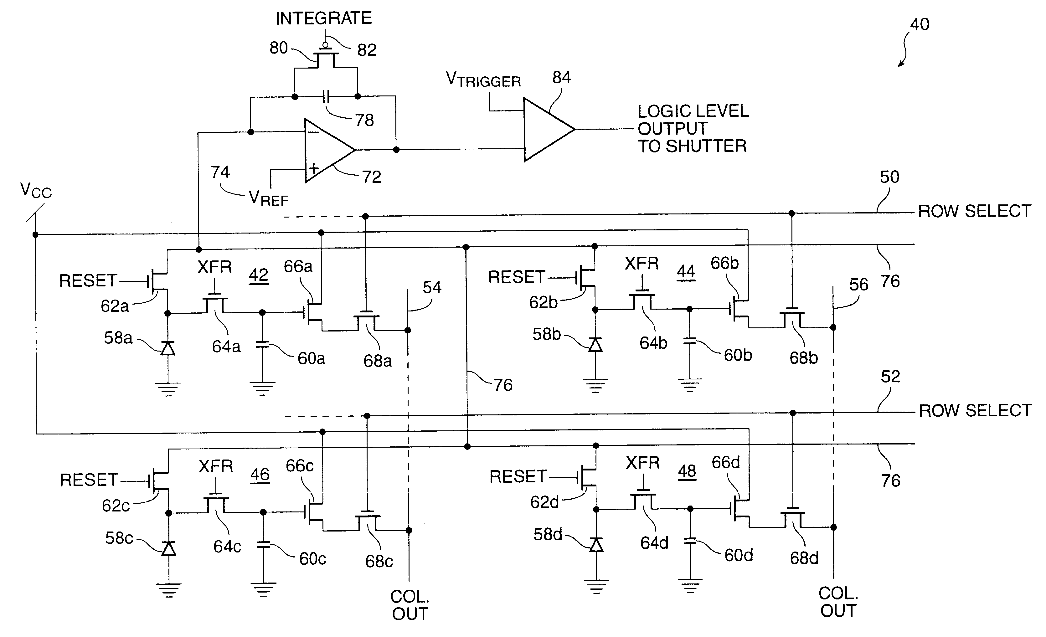
Frame-storage imaging arrays according to the present invention have the ability to begin and end an exposure interval very quickly under completely electronic control via timing logic signals. One aspect of the present invention exploits that capability by providing methods and circuits for detecting when the exposure is sufficient, and for automatically terminating the exposure interval very precisely. The present invention thereby responds to the actual light being received during the exposure interval, as detected by the actual detectors. This is believed to be an improvement over measuring the light with a separate detector or at a separate time.

The presently preferred embodiment of the invention takes advantage of the fact that the acti...


PUM


Abstract

A method for controlling the exposure of an active pixel array electronic still camera includes the steps of: integrating photocurrent in each pixel during an integration time period; collecting overflow charge from all pixels in the array during the integration time period; developing an overflow signal as a function of the overflow charge; and terminating the integration time period when the overflow signal exceeds a preset threshold level selected to represent a desired reference exposure level. Apparatus for performing the method of the present invention includes circuitry for integrating photocurrent in each pixel during a integration time period; circuitry for diverting and detecting overflow charge from all pixels in the array during the integration time period; circuitry for developing an overflow signal as a function of the overflow charge; and circuitry for terminating said integration time period when the overflow signal exceeds a preset threshold level selected to represent a desired reference exposure level.

Description

1. Field of the InventionThe present invention relates to electronic cameras employing solid state pixel sensor arrays. More particularly, the present invention relates to circuits and techniques for exposure control of such cameras and to exposure control of such cameras by means of overflow detection in arrays of active pixels.2. The Prior ArtPrior art exposure control techniques known to the inventors that use the actual image sensors during the actual exposure interval are of two types. Some prior art techniques integrate the total photocurrent by a common back-side electrode (anode) of a group of photodiodes--i.e., they integrate the substrate current to get an average light reading on the whole array. Other prior art techniques use nondestructive readout to sample selected pixels during the exposure interval, looking for an indication that some pixels are reaching a full-scale exposure.The first technique is tricky and difficult to implement, since the photocurrents are small ...

Claims


Application Information

Patent Timeline
Patent Type & Authority Patents(United States)
IPC IPC(8): H04N3/15H04N5/353H04N5/355H04N5/359H04N5/361H04N5/3745
CPCH04N5/353H04N5/35572H04N5/3559H04N5/3594H04N5/361H04N5/37452H04N25/53H04N25/587H04N25/59H04N25/623H04N25/63H04N25/771
Inventor MERRILL, RICHARD B.MEAD, CARVER A.LYON, RICHARD F.
Owner FOVEON
Why Eureka
Try Eureka