
Device and method for testing a device through resolution of data into atomic operations

Inactive Publication Date: 2002-09-24
SYNOPSYS INC
View PDF22 Cites 63 Cited by
  • Summary
  • Abstract
  • Description
  • Claims
  • Application Information

AI Technical Summary

Benefits of technology

to provide a test environment which will allow a test to be performed on different devices with a minimal amount of software revision to accommodate the different physical characteristics of the devices.
It is a further object of the invention to provide a test environment that allows separate development of the design and the test system.
It is a further object of the invention to provide a test environment which is modular, so that separate modules can be used independently as part of a test and the entire test environment does not need to be used for every test.
It is a further object of the invention to provide a test environment that does not require absolute timing for every event, e.g. transmitted and / or received actions on the bus, and thus to provide a system; which can test and simulate "random" events, as well as operate faster in certain cases due to a higher throughput of operations.
It is a further object of the invention to provide a test environment which can be used to perform a particular test on a particular device in different and / or multiple bus protocols, potentially more than one protocol in a given test, and to do so with a minimal amount of software revision to accommodate the different bus protocols.

Problems solved by technology

It is often the case that several different initiators will send out requests, and it is undeterminable which node will return responses to the requests.
Along with the differences between a transaction, there will be different delays in the system depending on how many nodes separate the source and destination nodes.

Method used


Image

  • Device and method for testing a device through resolution of data into atomic operations
  • Device and method for testing a device through resolution of data into atomic operations
  • Device and method for testing a device through resolution of data into atomic operations

Examples


first example

Asynchronous Transaction.

Each test file starts with an initial begin block. In actuality, several files are prepended and post-pended to the test file to make a "useable" Verilog module file.

initial

begin: one

The first section for all tests is an optional section for local parameters. In this file there are two parameters, Links_ld and Phys_Id. The Links_ld parameter is used for setting up the physical ID of the link core. This is used in writing the link ID control register.

parameter Links_Id=0;

parameter Phys_Id=1;

The next section is the local storage section. These are local registers and integers used for the test.

The integer A is used for an internal loop integer. It selects between 1394-1995 mode and 1394A mode.

Because these tests are valid for both protocols, we should test both protocols in this one test, therefore, we loop through the test twice, once in both modes.

The register bit rel_abs is used to switch between relative indexing and absolute indexing. This brings up the a...


PUM


Abstract

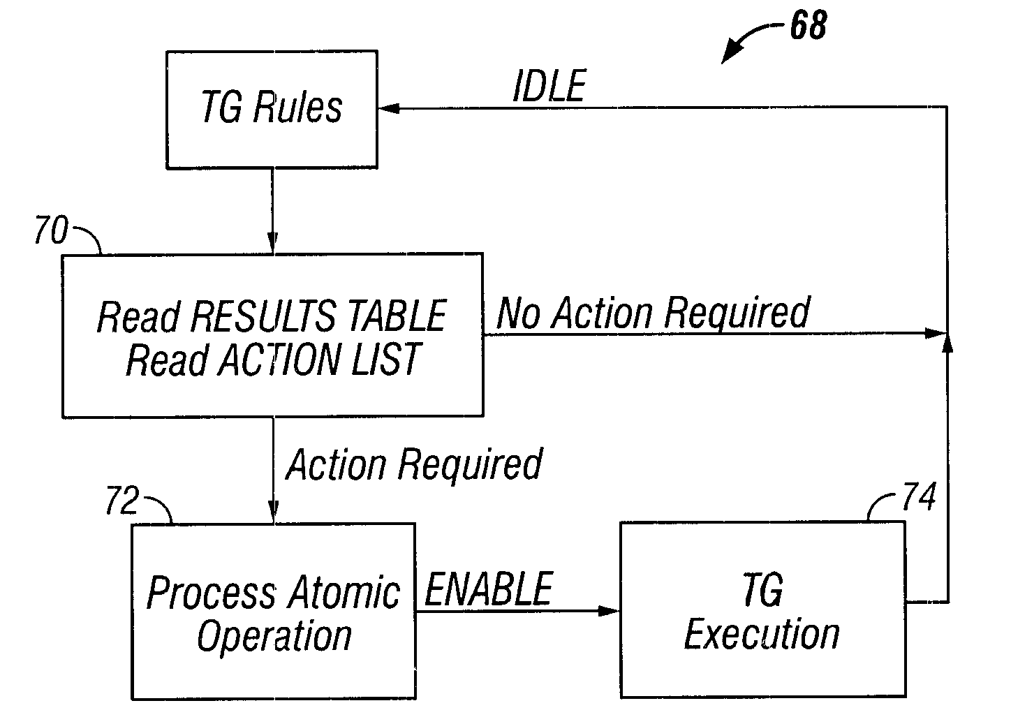
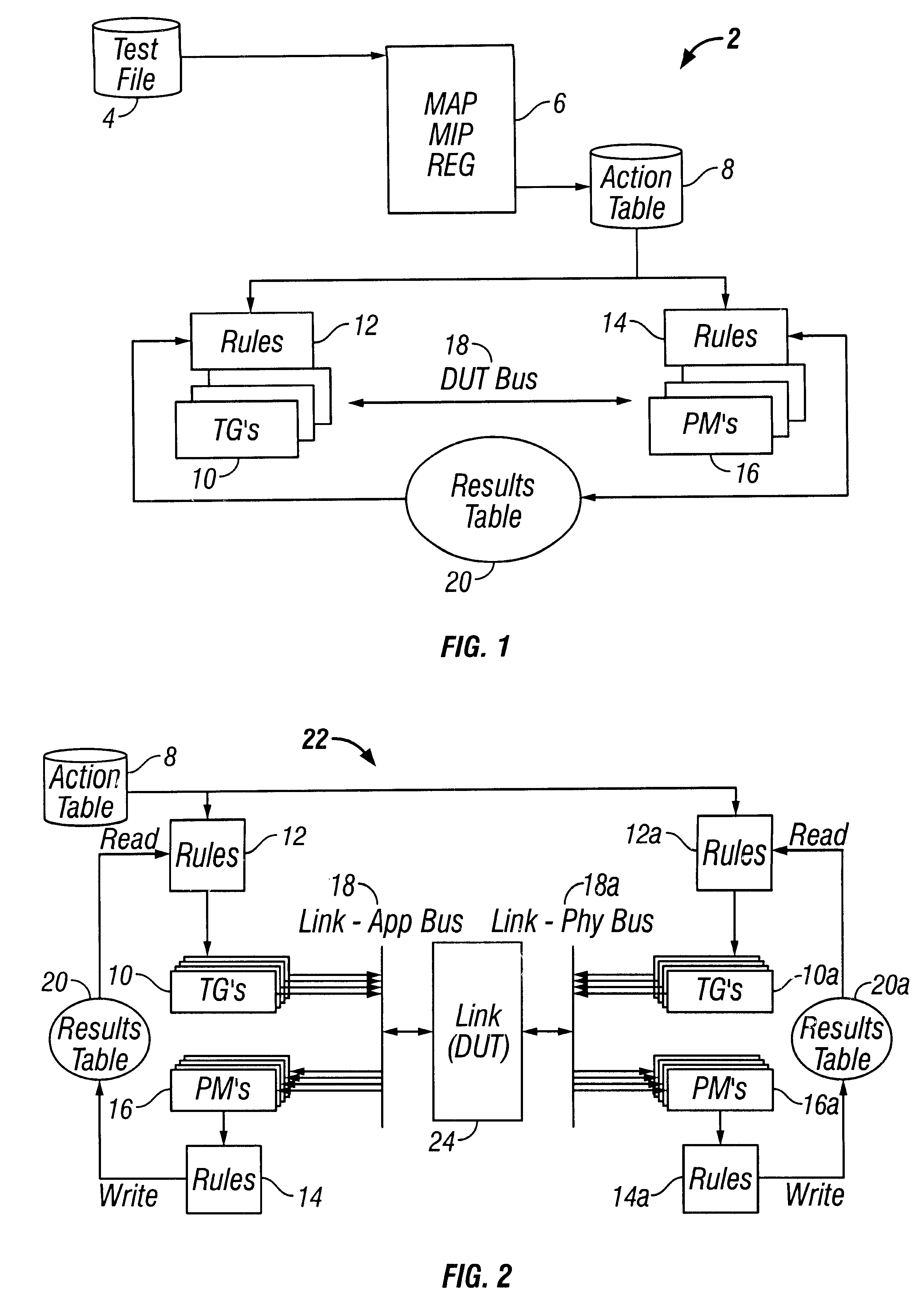
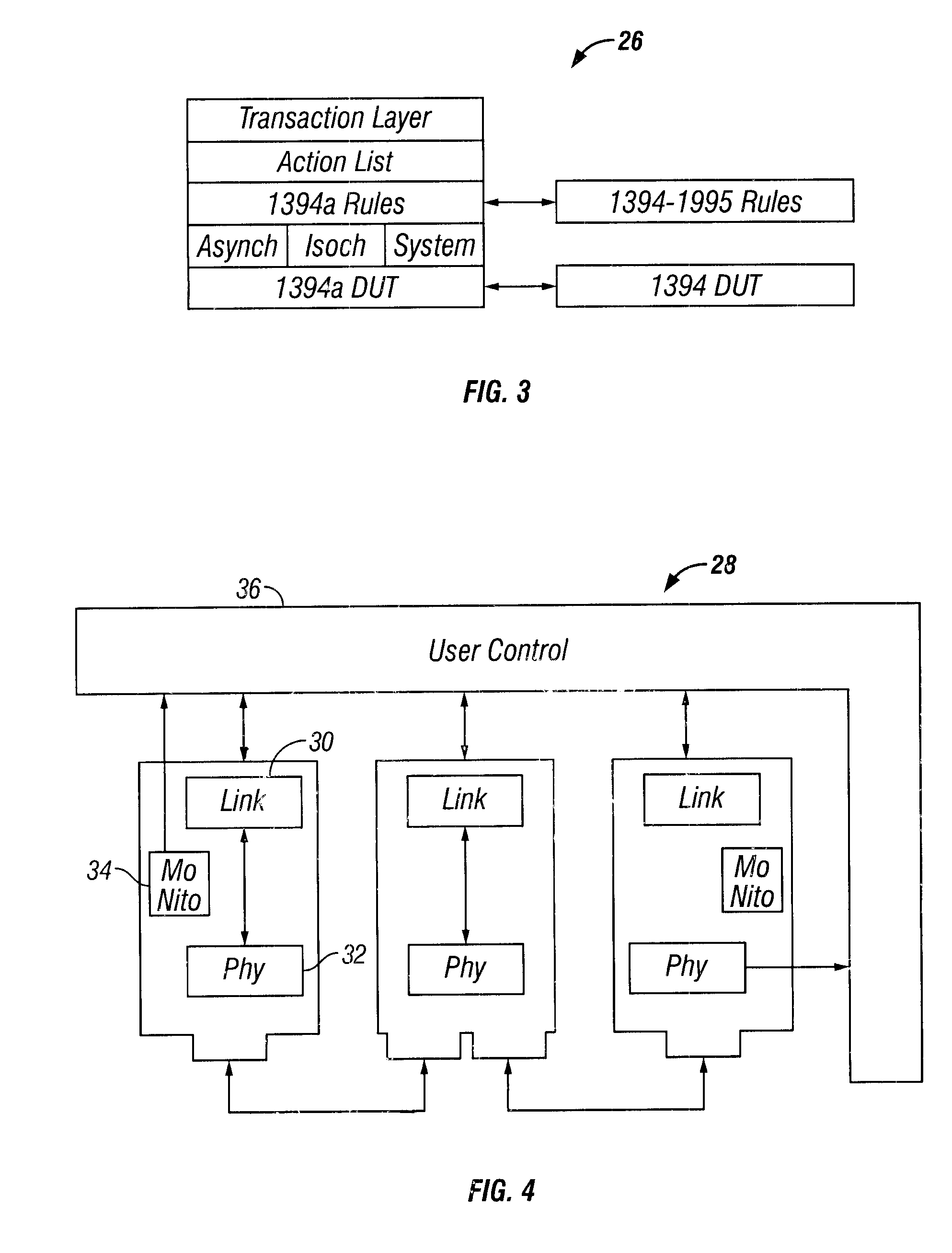
A method of testing a device includes monitoring an output of the device, wherein the output is generated by the device in response to an applied test command; and resolving the output into atomic operations, wherein the atomic operations are substantially the smallest constituent operations which are substantially independent of the device. The method is used to provide a simple, comprehensive test environment that effectively tests 1394a and 1394-1995 designs, for example, in Verilog. The test environment contains rules which completely characterize the behavior of different 1394 bus protocols as defined by the IEEE specifications. The test environment provides portability between different devices under test and between different protocols, automated closed-loop reconciliation of test commands and protocol requirements, topology independence, and out-of-order execution of instructions or relative sequencing. The test environment further allows failure injection, and separate and independent design of the device and a test system.

Description

Not applicable.1. Field of the InventionThe invention disclosed broadly relates to the field of testing integrated circuit designs, and more particularly relates to the field of testing the protocol compliance of designs (such as Verilog designs) of a link layer for either the 1394-1995 or the 1394a bus protocols.2. Description of the Related ArtIntegrated circuit ("IC") designs are commonly designed in software, such as Verilog. It is useful, therefore, to test the design in software as well. Accordingly, a variety of tools have been developed to facilitate both the design and the test of ICs in software. The design itself is also commonly broken into different components, and in such development schemes it is important to be able to test the individual components of the design.For applications that utilize either the 1394-1995 or the 1394a bus (collectively referred to hereinafter as the "1394 Bus"), many of the protocol functions can be developed independently of the application ...

Claims


Application Information

Patent Timeline
IPC IPC(8): H04L29/06H04L12/26
CPCH04L12/2697H04L29/06H04L43/50H04L69/03H04L9/40
Inventor PALEY, DANIEL NOAHKNECHT, MARK WILLIAM
Owner SYNOPSYS INC
Learn More