Device for calibrating distance-measuring apparatus

a technology for measuring apparatuses and devices, applied in distance measurement, instruments, and using reradiation, etc., can solve problems such as phase shift of signals, delay of signal generation, errors in distance measurement, and delay of all electronic components and lines

Inactive Publication Date: 2002-10-08
LEICA GEOSYSTEMS AG
View PDF18 Cites 90 Cited by
  • Summary
  • Abstract
  • Description
  • Claims
  • Application Information

AI Technical Summary

Benefits of technology

Specifically, avalanche photodiodes have about 100 times higher amplification than other photodiodes and hence a correspondingly high sensitivity. For this they require a very much higher and temperature dependent operating voltage in operation. Consequently, avalanche photodiodes must be operated with variable bias voltage dependent on the temperature. As a result of this, the capacitance of an avalanche photodiode changes with the varying bias voltage so that undesired phase shifts are caused. However, these phase shifts are equal both for the low-frequency measuring signal delivered by the avalanche photodiode and for the low-frequency calibration signal, owing to the electrical connection between frequency mixer and avalanche photodiode. Thus, the bias voltage of the avalanche photodiode, which varies as a function of temperature, is eliminated as a source of error for the distance value determined from the phase measurement.
Because reference and measuring beam are received not in succession but simultaneously and their mutual phase position is measured, a drift of the transmitter in calculating the difference between the phases is eliminated by calibration.
In general, the accuracy of the distance measurement is increased by this optoelectronic calibration, in particular with the requirements that only short measuring times are permitted and that the increased accuracy of measurement is achieved immediately after the apparatus has been switched on. In addition, the measuring times are reduced to about half that of the conventional successive measuring methods, since switching operations are dispensed with. The reliability of the apparatus, too, is improved by the invention since no mechanically movable components are necessary. Moreover, the omission of the mechanical switching device is advantageous for a handheld measuring apparatus, owing to the lower weight and volume. The associated lower manufacturing costs are also advantageous. Finally, the short measuring times permit a substantially larger number of measurements with a given battery charge.

Problems solved by technology

All electronic components and lines give rise to signal delays in the signal path of an optical distance-measuring device.
This results in particularly large signal delays which cause a phase shift of the signals and hence errors in the distance measurement.
A high accuracy of measurement with short measuring times immediately after switching on the apparatus is however not achieved.
In addition, many apparatuses are set up in such a way that at least the high-frequency electronics of the transmitter automatically switches off after a short waiting time at the end of a distance measurement, since said electronics consume a particularly large amount of electrical energy.
If a further measurement is required, the apparatus then switches on automatically, the associated thermal drift problems, as described above, being repeated.
Since, however, the operating voltage has to be adjusted as a function of the diode temperature, the phase position of the signal received and hence the measured value for the distance also inevitably change.
Finally, repeated mechanical switching during the measurement process results in high mechanical stresses and hence considerable wear of the moving parts.
Correspondingly complicated designs on the other hand in turn mean high manufacturing costs and generally a large weight and volume.
As a result of this, the capacitance of an avalanche photodiode changes with the varying bias voltage so that undesired phase shifts are caused.

Method used


Image

  • Device for calibrating distance-measuring apparatus
  • Device for calibrating distance-measuring apparatus
  • Device for calibrating distance-measuring apparatus

Examples


Embodiment Construction

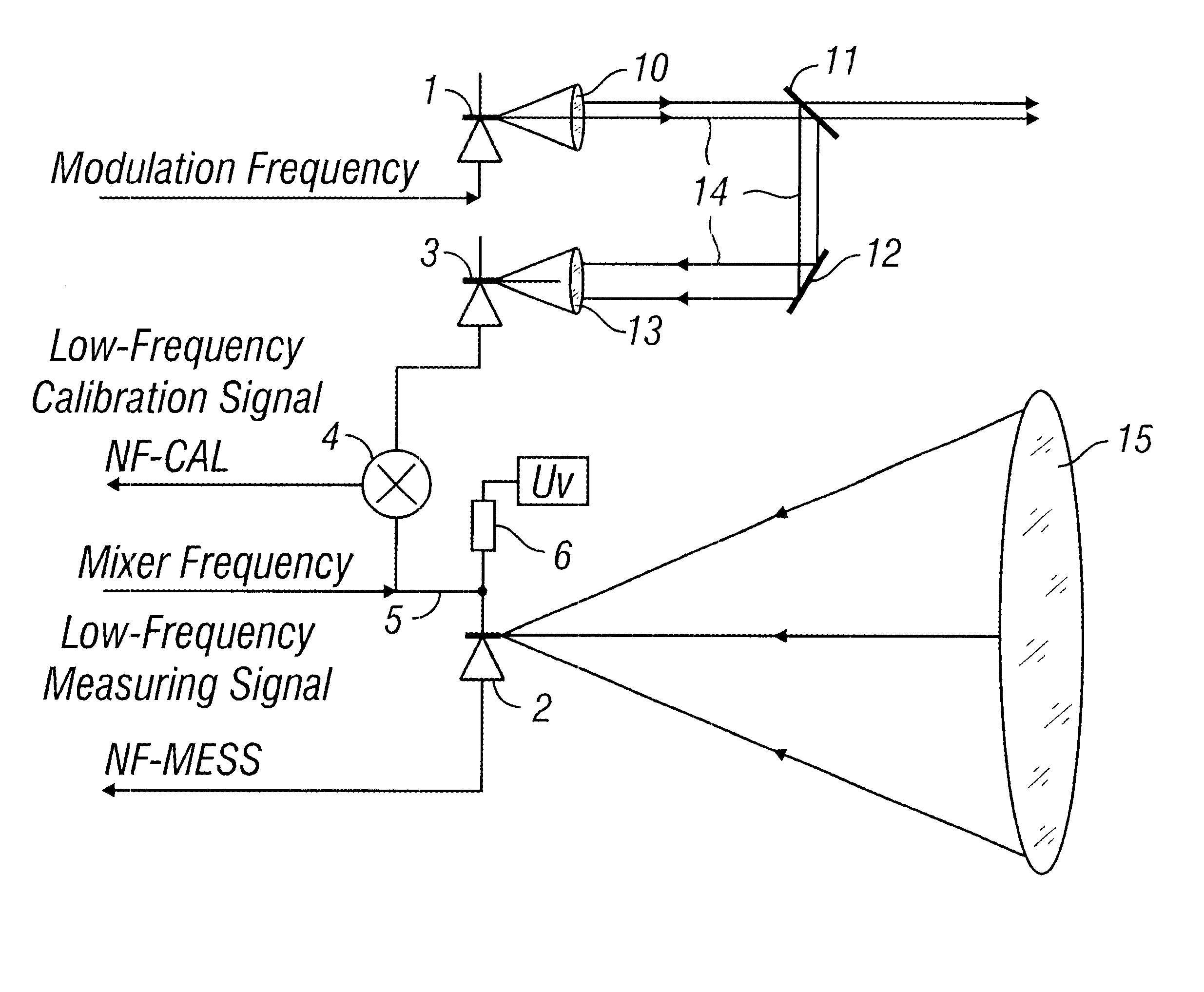
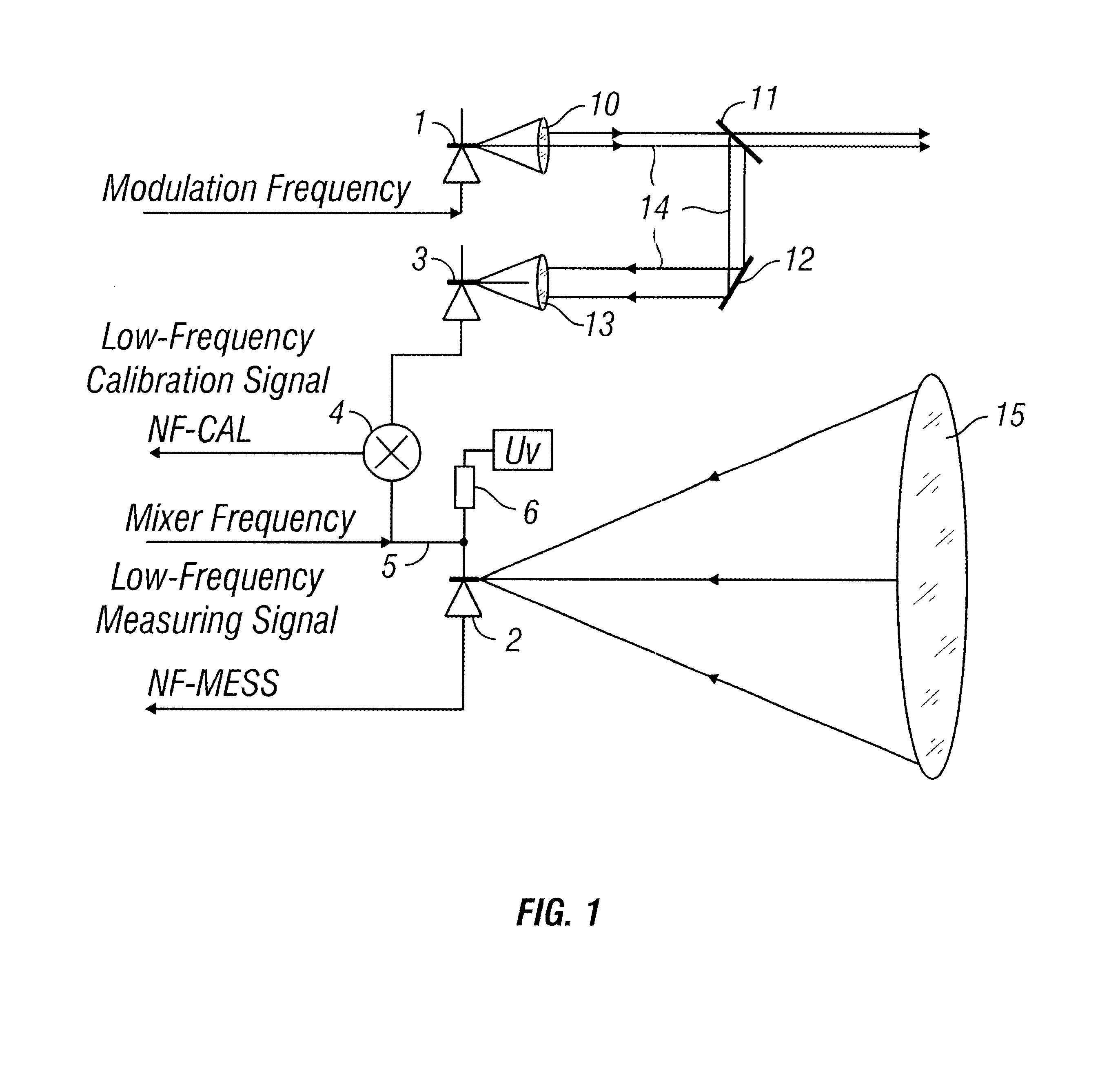
FIG. 1 schematically shows a distance-measuring apparatus according to the invention. The optical beam emitted by the transmitter 1 and collimated by an optical collimation means 10 is divided by a beam divider 11 into a measuring beam and into a reference beam. The measuring beam reaches an object which is to be measured and whose distance is to be determined. The beam reflected or scattered by the object to be measured is guided in the usual way via a receiving lens system 15 to a measuring receiver 2.

After covering a reference distance 14 which leads via the beam divider 11, a deflection mirror 12 and a lens system 13, the reference beam is received by a reference receiver 3. The reference distance 14 is the optical calibration distance of the distance-measuring apparatus. Depending on the space available in the apparatus, the reference distance 14 can of course be otherwise designed and, for example, the reference receiver 3 can be positioned directly after the beam divider 11. ...


PUM


Abstract

A transmitter emits high-frequency modulated optical radiation which is reflected by an object and is received by a measurement receiver. Part of the transmitter radiation is decoupled as reference radiation and guided via a calibration path to a reference receiver whose electrical signals are fed to a frequency mixer. The frequency mixer and avalanche photodiodes acting as measurement receivers of the measuring radiation are interconnected directly via an electrical connection line upon which a mixer frequency acts. As a result thereof, optoelectronic calibration which completely compensates for the temperature-dependent phase shifts of the avalanche photodiodes is possible. Additionally, the phase shifts generated in the reference and receiver signals by the temperature drifts of the transmitter compensate one another. The overall accuracy of the distance measurement can be increased, particularly for short measuring times and immediately after the apparatus has been switched on. Furthermore, in comparison with a successive mechanical calibration process, the measuring times are halved and advantages in terms of weight, cost, and reliability are afforded since a mechanical change-over device is dispensed with.

Description

1. Field of the InventionThe invention relates to a device for calibrating distance-measuring apparatuses.2. Description of the Related ArtThe distance-measuring apparatuses are commercially available as hand-held measuring apparatuses. Their distance measuring range is a few multiples of 10 m and they are used mainly in building surveying, for example for the 3-dimensional measurement of rooms. The transmitter emits an intensity-modulated beam. In general, wavelengths in the visible range are used, facilitating the aiming at the measuring points. The beam is reflected or scattered by the object to be measured and is picked up by the receiver. The distance from the object to be measured is obtained on the basis of the phase position of the modulated beam relative to the transmitter.It is known that the accuracy of measurement of these distance-measuring apparatuses is determined to a great extent by environmental influences and apparatus-related influences. For example, varying ambi...

Claims


Application Information

Patent Timeline
Patent Type & Authority Patents(United States)
IPC IPC(8): G01S7/48G01S7/497G01S17/32G01S17/36
CPCG01S7/497
Inventor GIGER, KURT
Owner LEICA GEOSYSTEMS AG
Why Eureka
Try Eureka