

Method for implementing a bist scheme into integrated circuits for testing RTL controller-data paths in the integrated circuits
- Summary
- Abstract
- Description
- Claims
- Application Information
AI Technical Summary
Benefits of technology
Problems solved by technology
Method used
Image

Examples
Embodiment Construction
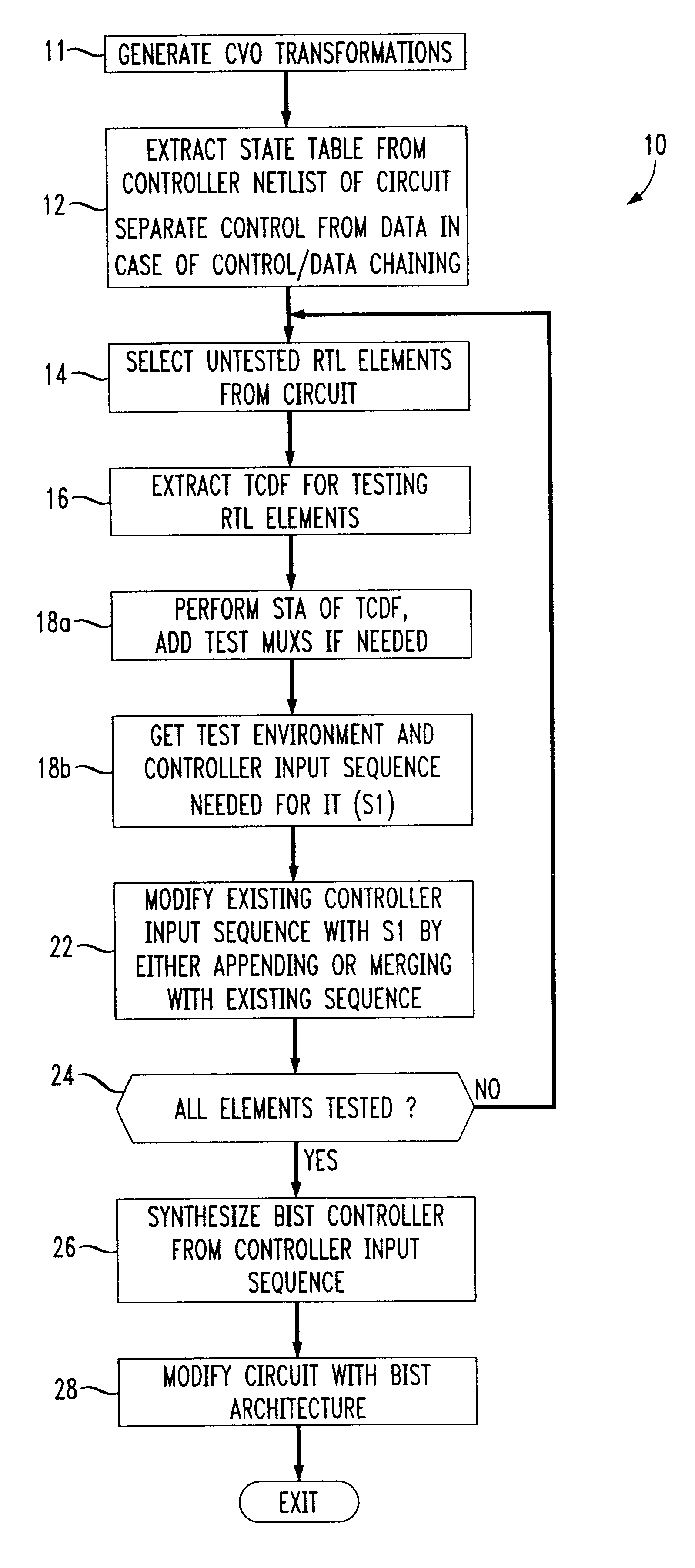
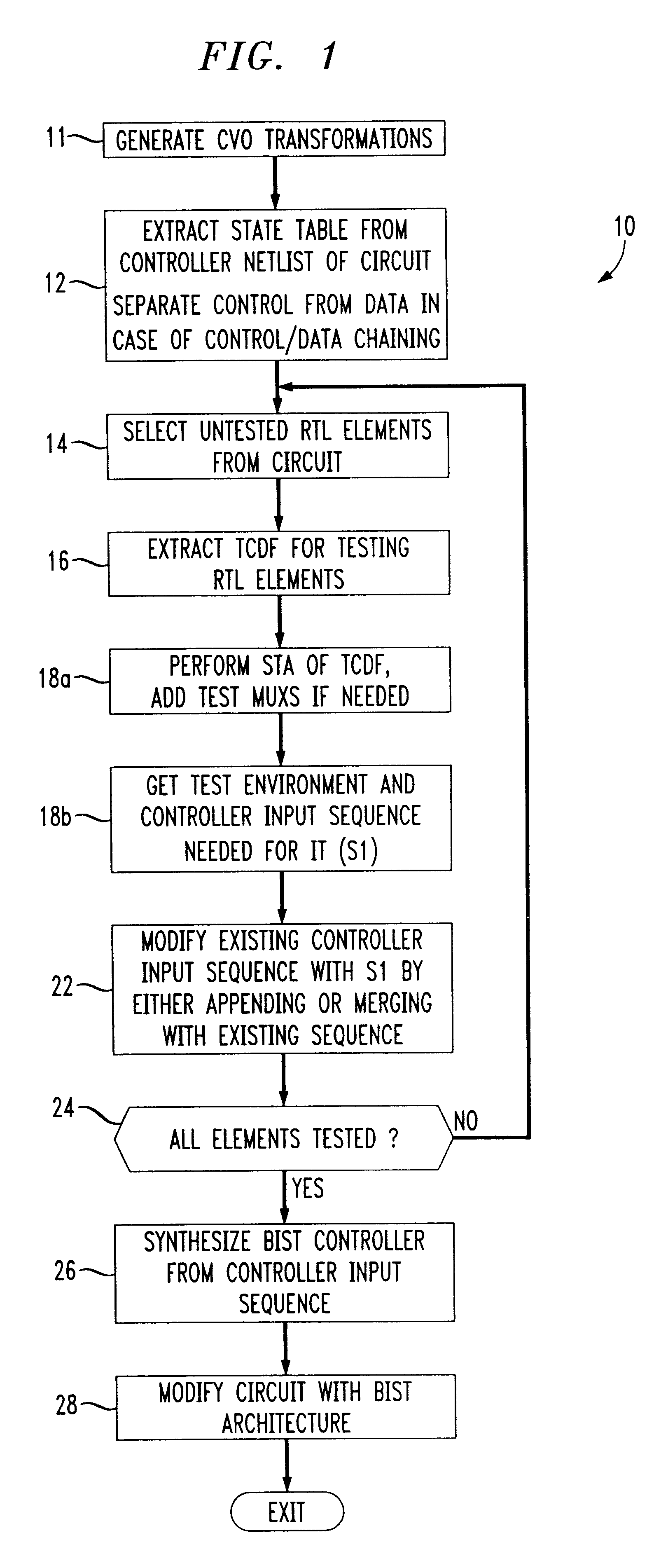
FIG. 1 is a flow diagram showing a general overview of a method 10 for testing RTL controller-data paths using BIST in accordance with an embodiment of the present invention. The following description of each step of the method 10 generally follows the flow of the overview provided in FIG. 1. The following terms are defined for clarity in understanding the following disclosure. An RTL circuit is generally the entire (or complete) circuit design in the register transfer level (RTL). An RTL module is a subcircuit of an RTL circuit and the RTL element is the lowest level of RTL component, for example, an adder, multiplier, etc.
Upon initiation of the method, the RTL modules in the library are examined and controllability, verifiability, and observability (CVO) transformation tables are generated for each of the RTL modules making up the RTL circuit in accordance with their respective functionality (step 11). These CVO transformations are used later in the invention method for symbolic j...
PUM
 Abstract
Description
Claims
Application Information