Navigational guidance via computer-assisted fluoroscopic imaging

Inactive Publication Date: 2002-10-22
MEDTRONIC NAVIGATION
View PDF165 Cites 870 Cited by
  • Summary
  • Abstract
  • Description
  • Claims
  • Application Information

AI Technical Summary

Problems solved by technology

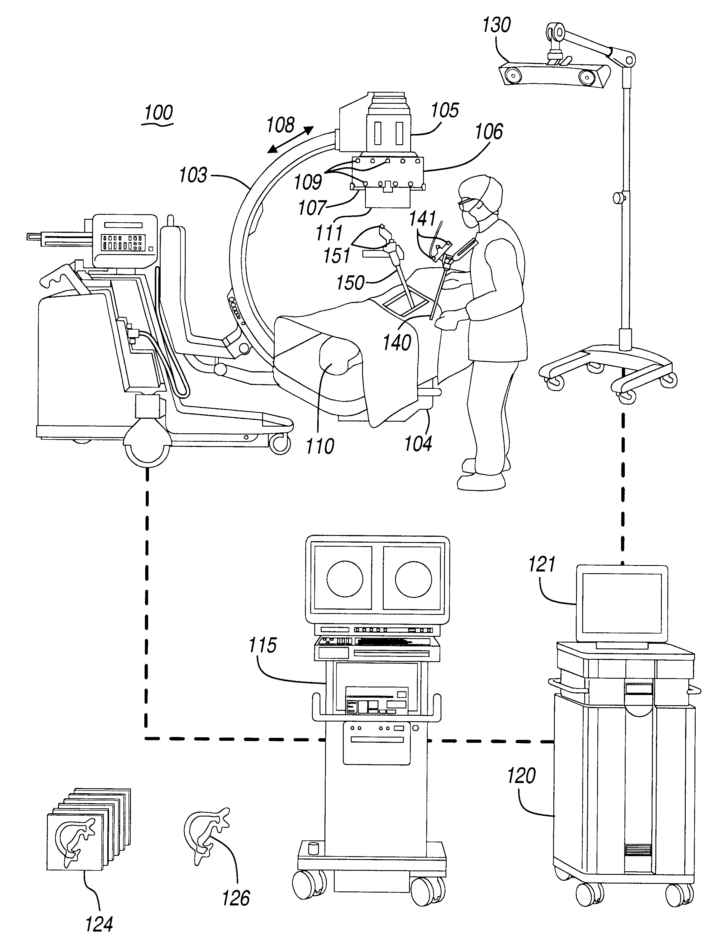
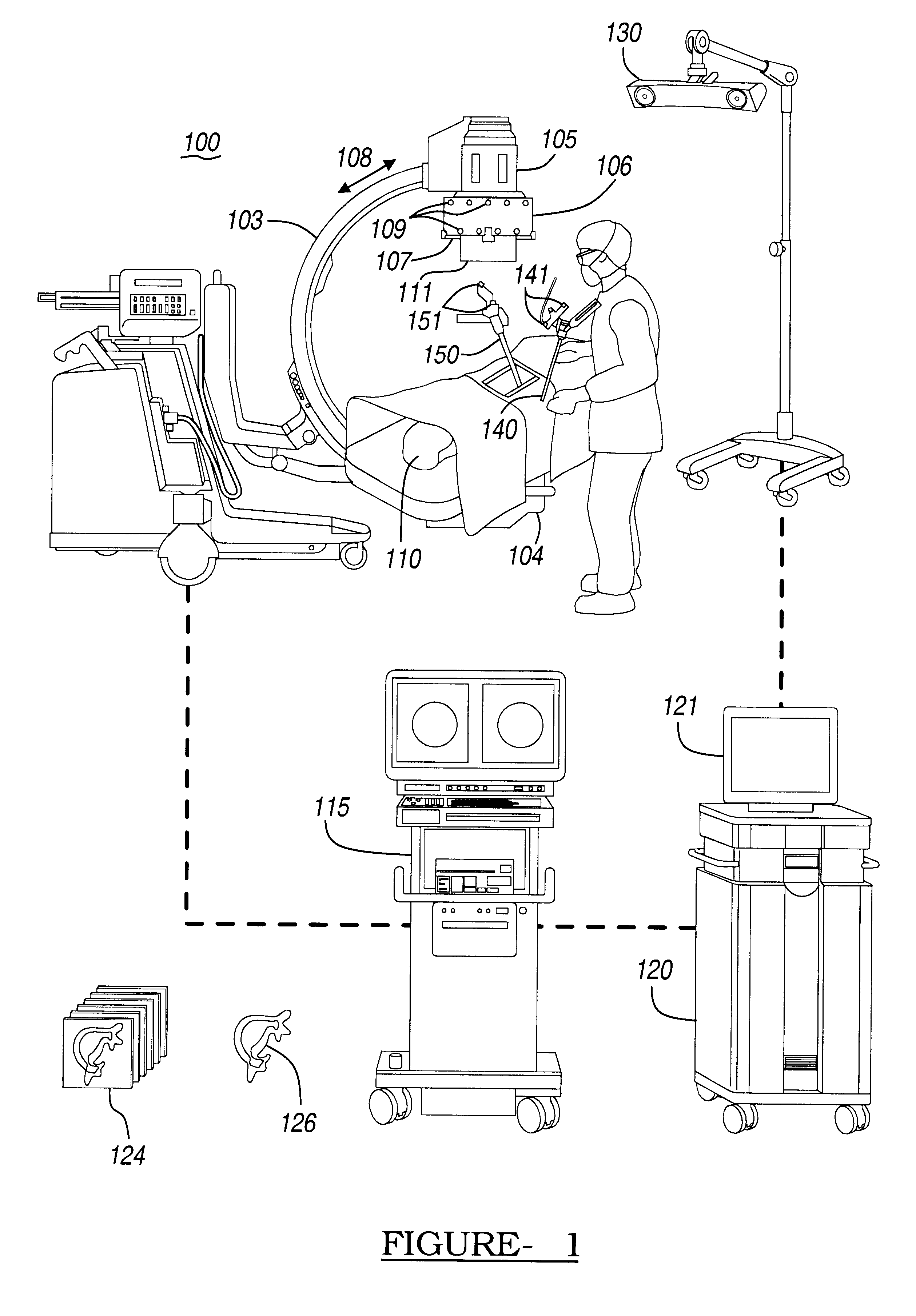
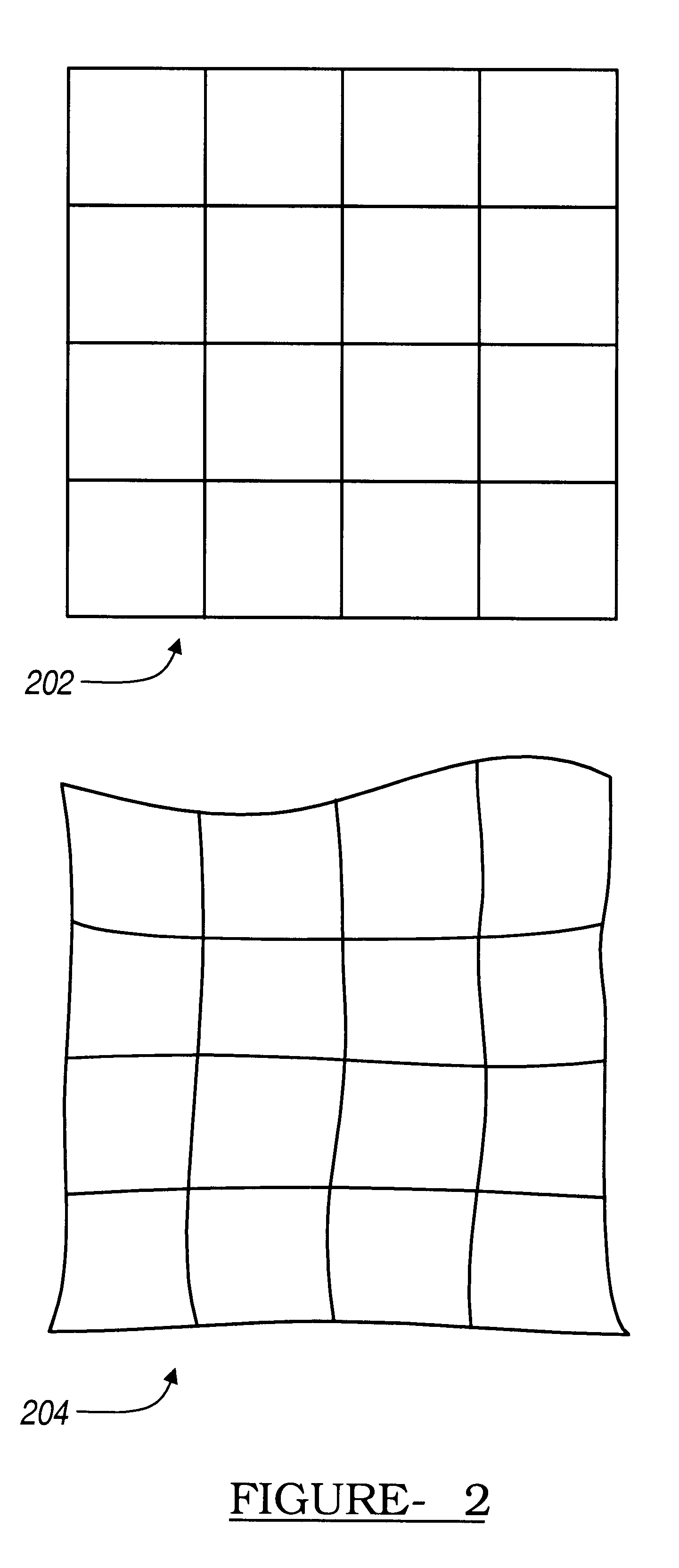
Raw images generated by receiving section 105 tend to suffer from undesirable distortion caused by a number of factors, including inherent image distortion in the image intensifier and external electromagnetic fields.
If imager 100 moves during the image acquisition process, or if imager 100 moves after image acquisition but before its position is recorded the calibration will be erroneous, thus resulting in incorrect graphical overlays.
When surgical instrument 140 is perpendicular to the plane of the fluoroscopic image, the graphical overlay of the surgical instrument essentially collapses to a point, making it difficult to view.
Generally, however, the axis of rotation of C-arm 103 is not inherently aligned with the axis that relates the complementary views, requiring the physician to perform a series of time consuming trial-and-error based adjustments of the fluoroscope's position through two or more axes of rotation.
While this method of directly interacting

Method used


Image

  • Navigational guidance via computer-assisted fluoroscopic imaging
  • Navigational guidance via computer-assisted fluoroscopic imaging
  • Navigational guidance via computer-assisted fluoroscopic imaging

Examples


example 2

Acquisition of an X-Ray View Down the Medial Axis of a Vertebral Pedicle

In certain clinical procedures, it may be desirable to acquire a fluoroscopic x-ray image view looking substantially straight down the medial axis of a vertebral pedicle. For the purposes of this example, a vertebral pedicle can be thought of as a cylinder, and the medial axis corresponds to the central axis of the cylinder.

FIG. 15A is an x-ray image in which the view direction of the imager is aligned with the medial axis of the pedicle (i.e., the medial axis of the pedicle is into the plane of the image. In this so-called "owl's eye" view, the pedicle appears as circle 1501 within the image. It is often difficult to precisely acquire this view using only fluoroscopic x-ray images, as it is difficult it to align the view direction of imager 100 with the medial axis of the pedicle using only fluoroscopic images.

Given an anterior / posterior fluoroscopic image view of the spine, such as the one shown in FIG. 15B, a...

example 3

Use of Digitally Reconstructed Radiography in the Placement of a Surgical Implant

With conventional fluoroscopic x-ray image acquisition, radiation passes through a physical media to create a projection image on a radiation sensitive film or an electronic image intensifier. Given a 3D CT data set, a simulated x-ray image can also be generated using a technique known as digitally reconstructed radiography (DRR). DRR is well known in the art, and is described, for example, by L. Lemieux et al., "A Patient-to-Computed-Tomography Image Registration Method Based on Digitally Reconstructed Radiographs," Medical Physics 21(11), pp 1749-1760, November 1994.

When a DRR image is created, a fluoroscopic image is formed by computationally projecting volume elements (voxels) of the 3D CT data set onto a selected image plane. Using a 3D CT data set of a given patient, it is possible to create a DRR image that appears very similar to a corresponding x-ray image of the same patient. A requirement for...

example 4

Obtaining a Particular Two-Dimensional View Direction Using Digitally Reconstructed Radiograph Images

The DRR technique can be used to provide guidance to the physician when acquiring an owl's eye view of a vertebral pedicle. Given a three-dimensional CT data set containing a vertebra and associated pedicle, the physician may use computer 120 to manually locate a three-dimensional representation of the pedicle's medial axis relative to the three-dimensional images of the vertebrae. Once this placement has been achieved, it is possible to synthesize an owl's eye view of the vertebrae based upon the view direction specified by the physician's selection of the three-dimensional medial axis. This synthetic image can then be displayed to the surgeon during surgery and used to guide the acquisition of an actual owl's eye view using the fluoroscope. By visually comparing fluoroscopic images taken while positioning the fluoroscope to the synthetic owl's eye view, the physician can acquire a ...


PUM


Abstract

Digital x-ray images taken before a surgical procedure by a fluoroscopic C-arm imager are displayed by a computer and overlaid with graphical representations of instruments be used in the operating room. The graphical representations are updated in real-time to correspond to movement of the instruments in the operating room. A number of different techniques are described that aid the physician in planning and carrying out the surgical procedure.

Description

The present invention is directed generally to image guided surgery, and more particularly, to systems and methods for using one or more fluoroscopic X-ray images to assist in instiuent navigation during surgery.DESCRIPTION OF THE RELATED ARTModern diagnostic medicine has benefitted significantly from radiology, which is the use of radiation, such as x-rays, to generate images of internal body structures. In general, to create an x-ray image, x-ray beams are passed through the body and absorbed, in varying amounts, by tissues in the body. An x-ray image is created based on the relative differences in the transmitted x-ray intensities.Techniques are known through which x-ray images are used to locate the real-time position of surgical instruments in the patient anatomy represented by the x-ray image without requiring x-rays to be continually taken. In one such system, as disclosed in U.S. Pat. No. 5,772,594 to Barrick, light emitting diodes (LEDs) are placed on a C-arm fluoroscope x-...

Claims


Application Information

Patent Timeline
IPC IPC(8): A61M25/01G06F19/00A61B19/00A61B6/12
CPCA61B6/463A61B6/547A61B19/5244A61M25/0105G06F19/3406A61B6/12A61B2019/504A61B2019/505A61B2019/507A61B2019/508A61B2019/5238A61B2019/5255A61B2019/5272A61B2019/566A61M2025/0166A61B2034/104A61B2034/2055A61B2034/2072A61B2034/256A61B34/20A61B2090/376A61B2034/105A61B2034/107A61B2034/108G16H40/63G16Z99/00
Inventor SIMON, DAVID A.SMITH, KURT R.FOLEY, KEVIN T.
Owner MEDTRONIC NAVIGATION
Why Eureka
Try Eureka