
Assay using porosity-reduction to inhibit migration

a technology of porosity reduction and migration inhibition, applied in the field of assaying analyte devices, can solve the problems of difficult manufacturing quality control, inability to manufacture nitrocellulose, and inability to homogeneous nitrocellulose production, etc., and achieve the effect of simple and cheap production

Inactive Publication Date: 2002-10-29
GENOSIS UK
View PDF13 Cites 63 Cited by
  • Summary
  • Abstract
  • Description
  • Claims
  • Application Information

AI Technical Summary

Benefits of technology

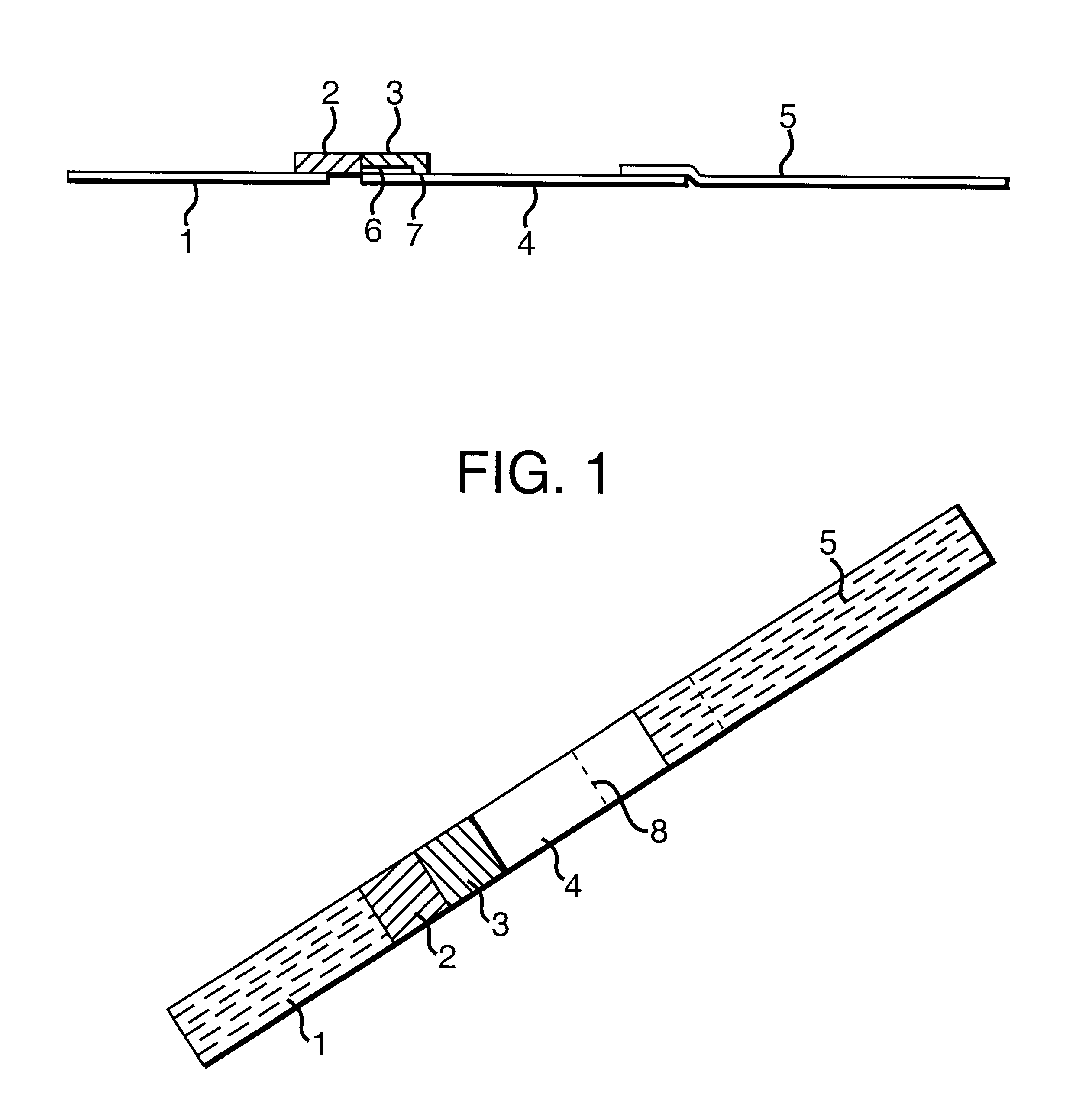
In some embodiments, the labelling zone and capture zone may be formed from a single piece of porous material, which contains a region of reduced pore size. By crushing or compressing a region of a porous material, for instance, the pore size can be reduced such that an analyte-bound label cannot enter the compressed region ie. to form a capture zone. As an alternative, the pores of the material could be partially blocked, to achieve the same effect.
The interface between the labelling zone and the capture zone is preferably narrow compared to the length of the capture zone. Where the labelling zone and the capture zone are formed from strips of overlapping material, a narrow interface between them can be achieved by the presence of a non-porous material covering the majority of the overlap. By ensuring that the interface between the labelling zone and the capture zone is narrow, the analyte-label complex is focused at the junction of the labelling zone and the capture zone, giving a sharper signal.
The device of the invention can be produced simply and cheaply, conveniently in the form of a test strip or dipstick. Furthermore, it can be used very easily, for instance by the home user. The invention thus provides an assay device which can be used at home as a basic screen of, for instance, male fertility.

Problems solved by technology

This is unsatisfactory in many respects.
Firstly, manufacturing quality control is difficult.
Nitrocellulose manufacture is not, however, homogeneous.
Quality control of the solid phase antibody is therefore limited to testing a statistical sample of devices from the same, but heterogeneous, batch, and assuming that the whole batch will perform within specific tolerances.
Secondly, they are relatively cumbersome to manufacture.
Thirdly, antibody is immobilised by spraying a solution onto a membrane.
Tests that rely on a comparison of colour intensity between control and detection lines, such as ovulation prediction kits, may therefore give false results.
Furthermore, application by spraying inevitably leads to diffusion into the membrane, leading to a more diffuse and less focused detection signal.
Fourthly, the sensitivity of the devices is limited by their format.
The complex passes over the capture antibody for a short time, however, thus imposing constraints on the design of the test and its performance characteristics.
The short reaction time decreases sensitivity, and also means that high affinity capture antibodies are required.
Finally, the shelf-life of these test devices is often limited by the collapse of the immobilised capture antibody onto the membrane over time.

Method used


Image

  • Assay using porosity-reduction to inhibit migration
  • Assay using porosity-reduction to inhibit migration
  • Assay using porosity-reduction to inhibit migration

Examples


example 2

Qualitative Sperm Testing

In a test experiment, two samples were tested--the first was a sample of motile spermatozoa in HEPES buffer (obtained by indirect swim up from the ejaculate of a fertile man), and the second was just HEPES buffer. 75 .mu.l of each sample was placed on the absorbent pad (3) of two separate devices, and these were placed in separate wells, each containing 75 .mu.l HEPES.

After 15 minutes, the device used with the first sample had developed two clear red lines on membrane (4), the first about 1 mm above the absorbent pad (3), the second at line (8). The other device, however, contained a single red line at line (8). The device is thus able to capture spermatozoa mechanically around the `choking zone`.

example 3

Quantitative Sperm Testing

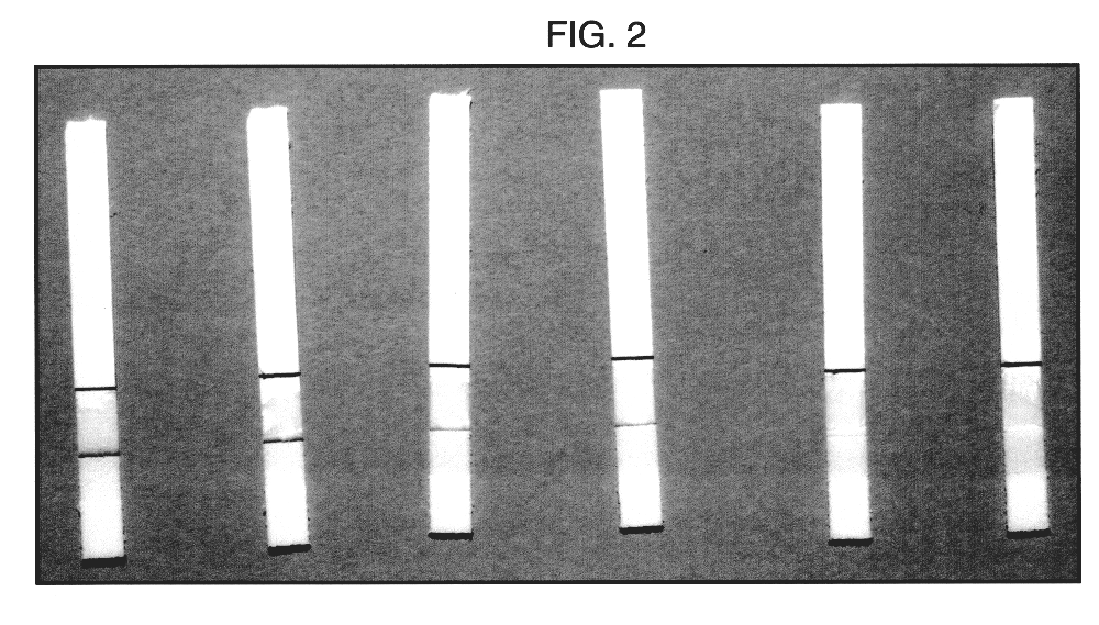
In a further experiment, a sample of motile spermatozoa in HEPES buffer was obtained by indirect swim up from the ejaculate of a fertile man. The number of motile sperm per ml in the HEPES portion of the swim up was established using a counting chamber and found to be 3.5 million. This sample was diluted with HEPES to give four further samples with 2, 1, 0.5 and 0.25 million sperm per ml respectively. 75 .mu.l of each of these five samples were placed on the absorbent pads (3) of five separate devices and these were placed in separate wells containing 75 .mu.l HEPES. Buffer alone was used as a control.

After 15 minutes, each of the devices had developed two clear red lines on membrane (4), the first about 1 mm above the absorbent pad (3), the second at line (8). As clearly shown in FIG. 2, however, the intensity of the first line decreased as the number of spermatozoa in the sample decreased by dilution. No first line was visible on the control. The device i...


PUM

PropertyMeasurementUnit
pore sizeaaaaaaaaaa
pore sizeaaaaaaaaaa
pore sizeaaaaaaaaaa

Abstract

Device for assaying an analyte, comprising a labelling zone, where a label can bind to the analyte, in communication with a capture zone, wherein the pore size of the capture zone is such that label which is not bound to the analyte can migrate therethrough, whereas label which is bound to the analyte cannot. During migration from the labelling zone (large pore size) to the capture zone (small pore size), unbound label can pass into and through the capture zone, whereas bound label will be captured at the junction of the labelling zone a the capture zone. The device relies upon the label being smaller than the analyte, such that free label is not retarded by the capture zone. It is particularly suitable for assying analytes such as spermatozoa, which are large in comparison with a label such as a labelled antibody.

Description

This invention relates to assay devices for measuring analytes. In particular, it relates to devices which capture analytes mechanically within a porous material, rather than using conventional immuno-capture techniques.The format of the standard rapid test lateral flow device has remained unchanged for around ten years. Typically, the device will comprise a nitrocellulose strip. Sample is applied to an application zone, from which it flows by capillary action through a zone containing a visibly-labelled antibody specific for the analyte in question. Free and bound label continue to migrate to a capture zone, where immobilised antibody specific for the analyte binds the analyte-label complex. Free label (unbound antibody) continues to migrate, leaving an analyte-specific signal in the capture zone. These types of lateral flow device are disclosed in, for example, EP-A-0284232. Numerous variations to the basic assay have been described, including those in WO92 / 12428, EP-A-0613005, WO...

Claims


Application Information

Patent Timeline
Patent Type & Authority Patents(United States)
IPC IPC(8): G01N33/543G01N33/558
CPCG01N33/54386G01N33/558Y10S436/808Y10S435/805Y10S436/81G01N33/54388
Inventor BARRADINE, MARTINGURMIN, TRACEY
Owner GENOSIS UK
Learn More