
S-video signal loss compensation processing apparatus and method

Inactive Publication Date: 2002-11-12
GORDON J GOW TECH
View PDF20 Cites 14 Cited by
  • Summary
  • Abstract
  • Description
  • Claims
  • Application Information

AI Technical Summary

Benefits of technology

It is an object of the present invention to provide enhancement of an S-video signal, containing luminance and chrominance (chroma) information, for delivering an enhanced S-video signal over a transmission line selected by the viewer for viewing on a monitor displaying a desirable image. It is further an object of the invention to provide a manually adjustable enhancement to the S-video signal for delivery of the S-video signal over lengthy transmission cables without signal degradation. It is further an object of the invention to provide transmission of a source video signal to a plurality of monitors while permitting adjustment of each signal for providing a pleasing picture on each monitor regardless of differing transmission line lengths between monitors and the video source.
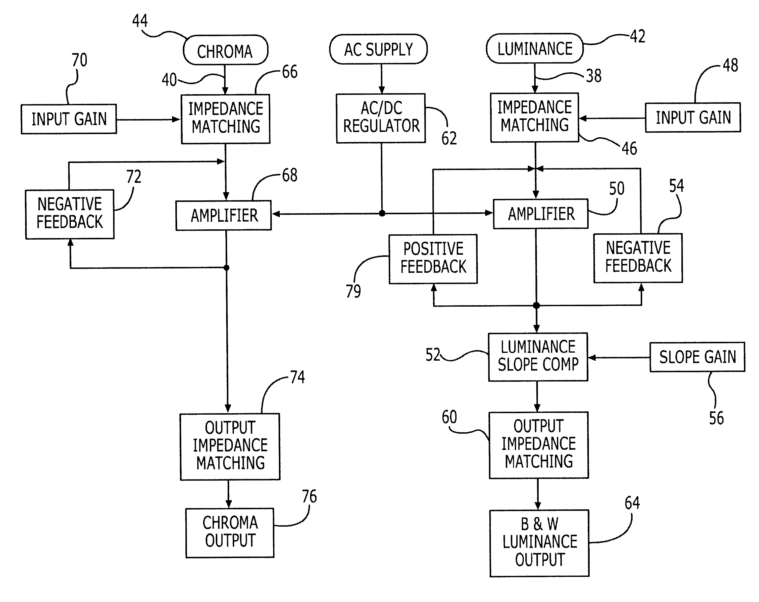
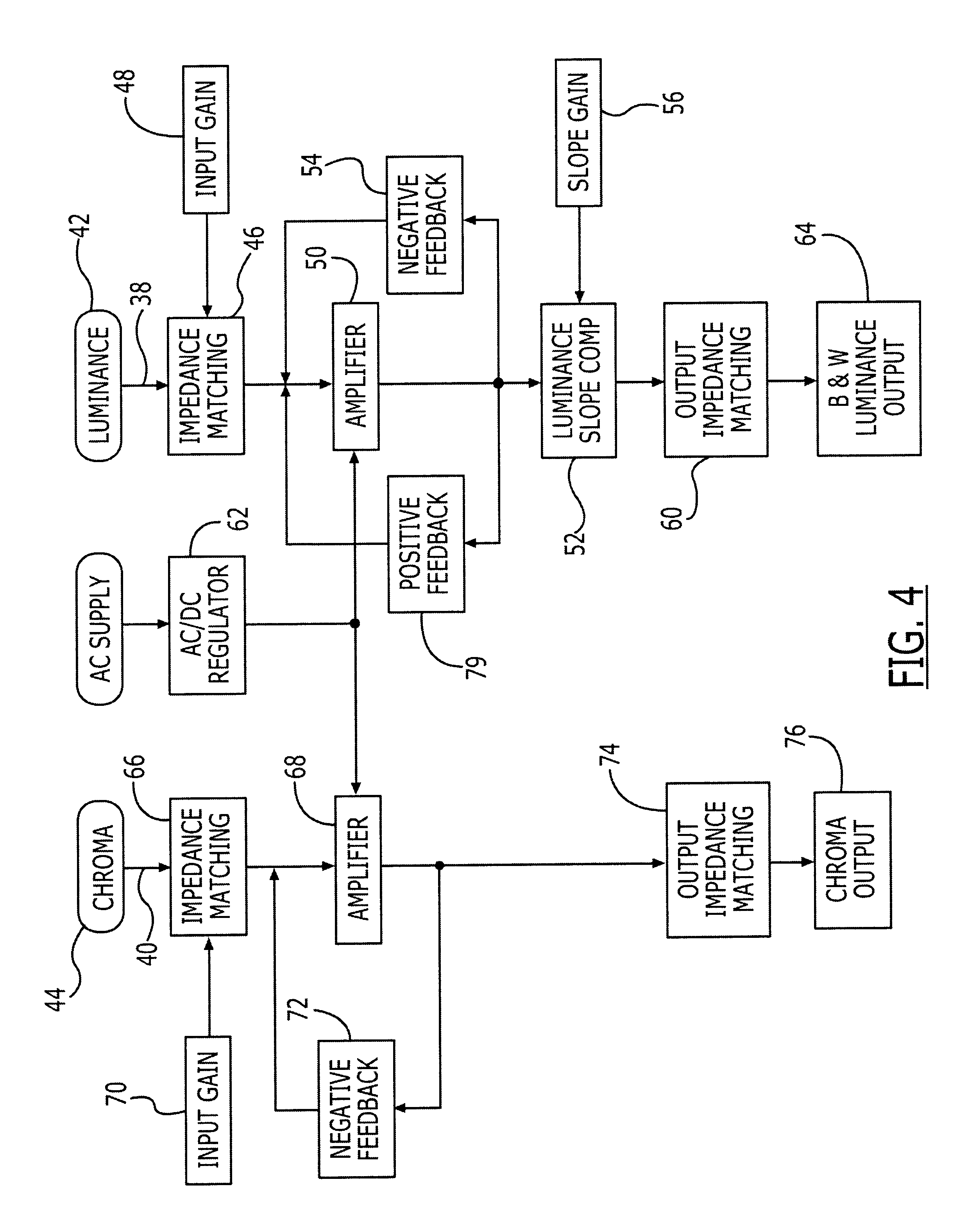
The present invention is directed to S-video signal compensation for providing adjustable electronic compensation to maintain picture quality of an S-video signal transmitted over lengths of S-video cable, and provides embodiments, by way of example, with NTSC and HDTV video signal bandwidths. One preferred embodiment of the present invention provides a single S-video input and single S-video output with a dedicated set of controls including a chroma gain, luminance, gain, and cable compensation control, thus allowing for a precise and customized calibration of the S-video signal. An alternate embodiment provides for multiple inputs and outputs. S-video signal compensation provided is useful for broad bandwidths needed in a typical video signal envelope. With a frequency response from DC to 20 MHZ, the S-video compensators of the present invention are capable of increasing gain with little or no distortion or noise either in luminance or chroma signal information. The embodiments of the present invention, herein described by way of example, provide a full complimentary output stage eliminating the need for coupling capacitors that could cause phase and frequency errors. Plus and minus power supplies feed highly accurate DC regulators, providing perfect operation even with AC voltages as low as 80 volts. Large filter capacitors eliminate the 120 hertz hum before regulations starts. Channel separation is achieved and is more critical than for audio signals because of the high probability of beating interference and oscillation. A unique slope amplifier is incorporated within the luminance stage to correct for any frequency degradation caused by connecting cables.
By way of example for one embodiment, with a positive feedback signal across the amplifier and a high frequency band pass filters, both adjustable, a user can adjust the video receiver to the same quality one could achieve by using a one meter length of the highest quality cable. Further, basic off-the-shelf cable such as standard shielded telephone cable is successfully used to transmit the video signal. A positive feedback resistor (potentiometer) and capacitor network provides an increased signal amplitude to achieve a desirable high frequency response while a second resistor (potentiometer) and capacitor network produce an upper to mid range slope or adjustment in frequency response to accommodate white balance and detail for a strong mid to upper frequency response driver offering signal nourishment needed to produce a preferred S-video signal for a vivid picture after experiencing transmission line loss.
By cloning a preferred embodiment, as is described in the detailed description section of this specification, an S-video distribution system is provided. The input of the distribution system is coupled directly through input gain potentiometers for both chrominance and luminance signals. The constant value of the potentiometers used offer a fixed input impedance satisfying the incoming source. Since both luminance and chrominance are now adjustable, each monitor can be adjusted for luminance, chrominance, and resolution, keeping each monitor in check for quality. An additional summing amplifier is provided to reproduce a composite output to meet a need for this format in anticipated field use. Two amplifiers having unity gain buffer the incoming S signal for providing a slave output to run additional distribution systems. This gives the user multiple channels, slave channels, and composite channels. By using a one ampere power supply, the need for extra supplies for each system is eliminated.
The present invention includes a correction system for handling the tough demands for quality video signal transmission associated with S-video applications. With a video amplifier having a gain of 6 dB and varying luminance signal frequency response over a particular frequency range using a bandpass filter, an output luminance signal is provided that has gain and adjustment sufficient for delivering a quality signal over a transmission line to a monitor. With a preselected gain and preselected frequency response, it is now possible to transfer a luminance signal through transmission cable having lengths ranging upwards to 150 and 300 meters while being able to maintain excellent picture quality.

Problems solved by technology

By combining these signals, the quality of the final signal available is reduced because precise decoding for viewing a final image has yet to be achieved.
This provided the color bandwidth needed but at the same time limited the upper end frequency response for luminance.
Separating the luminance and chrominance signals improves picture quality but it is well known that such luminance and chrominance information is limited to transmission over cable lengths within a few meters before significant degradation of the signal information makes the picture unacceptable to the user or viewer.
As a result, voids are produced between these side band clusters that are not used.
The S type video transmission cable that became a standard was small and produced an inadequate impedance match, high capacitance, and a high resistance which caused the video output, frequency response, and chrominance to be limited.
The industry immediately discounted the idea of using the S-video signal because of the poor reliability and significant signal line loss.
The S-video signal carried the high frequency component information for providing a picture pleasing to the viewer but it is this high frequency information that is quickly lost or degraded within relatively short cable transmission runs.

Method used


Image

  • S-video signal loss compensation processing apparatus and method
  • S-video signal loss compensation processing apparatus and method
  • S-video signal loss compensation processing apparatus and method

Examples


Embodiment Construction

The present invention will now be described more fully hereinafter with reference to the accompanying drawings, in which preferred embodiments of the invention are shown. This invention may, however, be embodied in many different forms and should not be construed as limited to the embodiments set forth herein. Rather, these embodiments are provided so that this disclosure will be thorough and complete, and will fully convey the scope of the invention to those skilled in the art. Like numbers refer to like elements throughout.

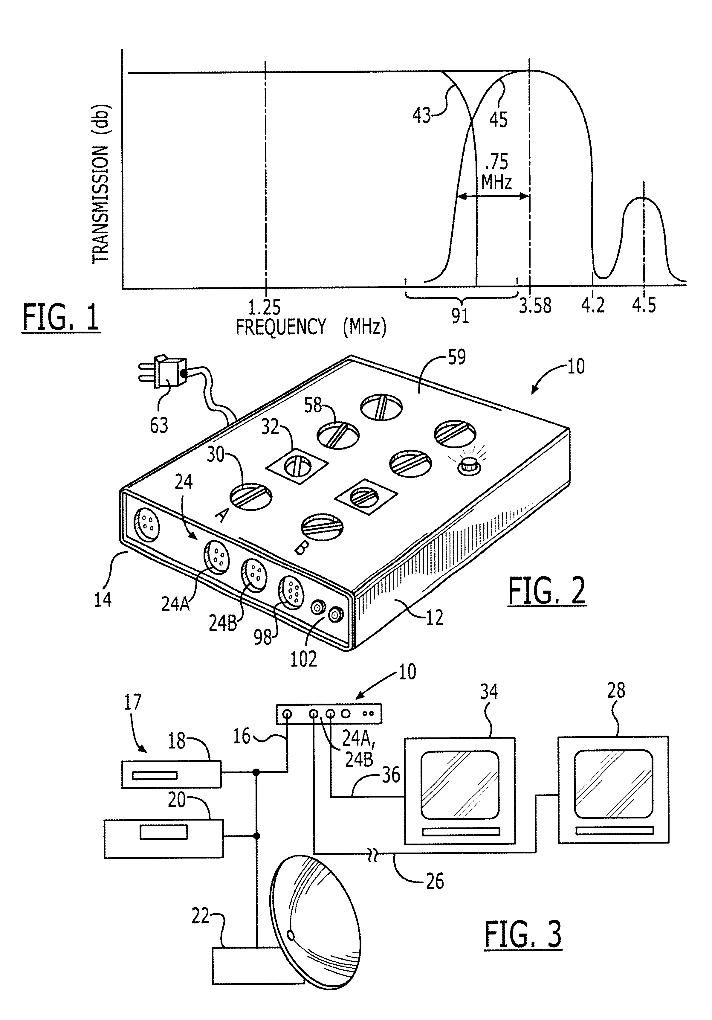
Referring initially to FIGS. 2 and 3, a video signal processing apparatus 10 is provided within a housing 12 having input connector means including an input terminal 14 for receiving a cable 16 carrying an S-video signal from a video source 17 such as a video disk player 18, video tape player 20, or other systems 22 such as a digital satellite system (DSS). As will be further detailed, the apparatus 10, in one embodiment of the present invention provides multipl...


PUM


Abstract

In an S-video signal processor, the luminance signal is amplified and adjusted over selected frequency ranges using a parallel signal for shaping the S-video signal response and permitting the S-video signal to be transmitted over exceptionally long transmission lines while providing a quality picture. In separate channels, chrominance and luminance signals are amplified and impedance matched. A luminance band pass filter permits manual adjustments to a lower range of video signal frequencies and thus changes to white level picture information. One version of the S-video signal processor includes a positive feedback network which permits user adjustments in an upper video signal frequency range having picture super detail information for providing a picture of high resolution and thus pleasing to the user. In a second version a compensation amplifier is used to alter the frequency response of the luminance signal. A clear picture, brighter and sharper, rather than simply a brighter picture is available whether transmitted over a few or few hundred feet from a video source to a video monitor.

Description

The present invention relates generally to an apparatus for transmitting an S-video signal from a video source over a transmission line having a length typically detrimental to the S-video signal and the processing of the S-video signal for enhancing the signal within selected frequency bands for overcoming transmission line loss. More particularly, the invention relates to the processing of chrominance and luminance signal components for enhancing brightness and resolution typically reduced through the transmission line loss.As is well known in the television and video industry, a composite video signal includes luminance and chrominance components that are combined or encoded, such as in an American standard signal established by the National Television System Committee (NTSC) of the Federal Communications Committee (FCC). By combining these signals, the quality of the final signal available is reduced because precise decoding for viewing a final image has yet to be achieved. The ...

Claims


Application Information

Patent Timeline
IPC IPC(8): H04N7/10H04N5/20
CPCH04N5/20H04N7/102H04N7/106
Inventor BOCCACCIO, JEFFREY A.
Owner GORDON J GOW TECH
Learn More