
Method and apparatus for separating and recovering perfluoro compound

a perfluoro compound and perfluoromethyl sulfonate technology, applied in the direction of halogenated hydrocarbon separation/purification, halogenated hydrocarbon preparation, separation process, etc., can solve the problems of ozone layer depletion, ozone layer deterioration, and the inability to reliably and reliably determine the output of perfluoromethyl sulfonate, so as to reduce the pressure difference, maximize the pressure governing function, and improve the flow rate control function

Inactive Publication Date: 2002-11-19
DAIDO AIR PROD ELECTRONICS
View PDF18 Cites 13 Cited by
  • Summary
  • Abstract
  • Description
  • Claims
  • Application Information

AI Technical Summary

Benefits of technology

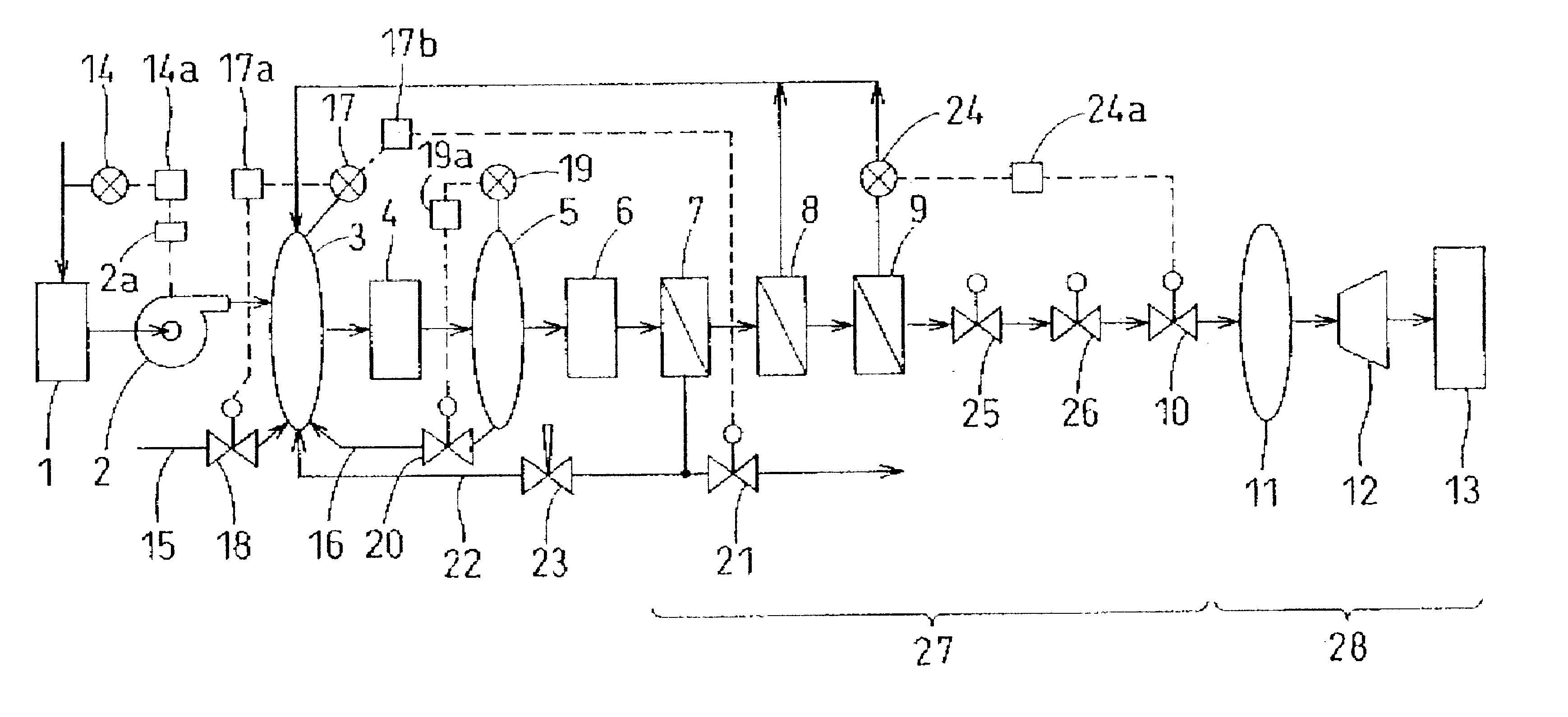
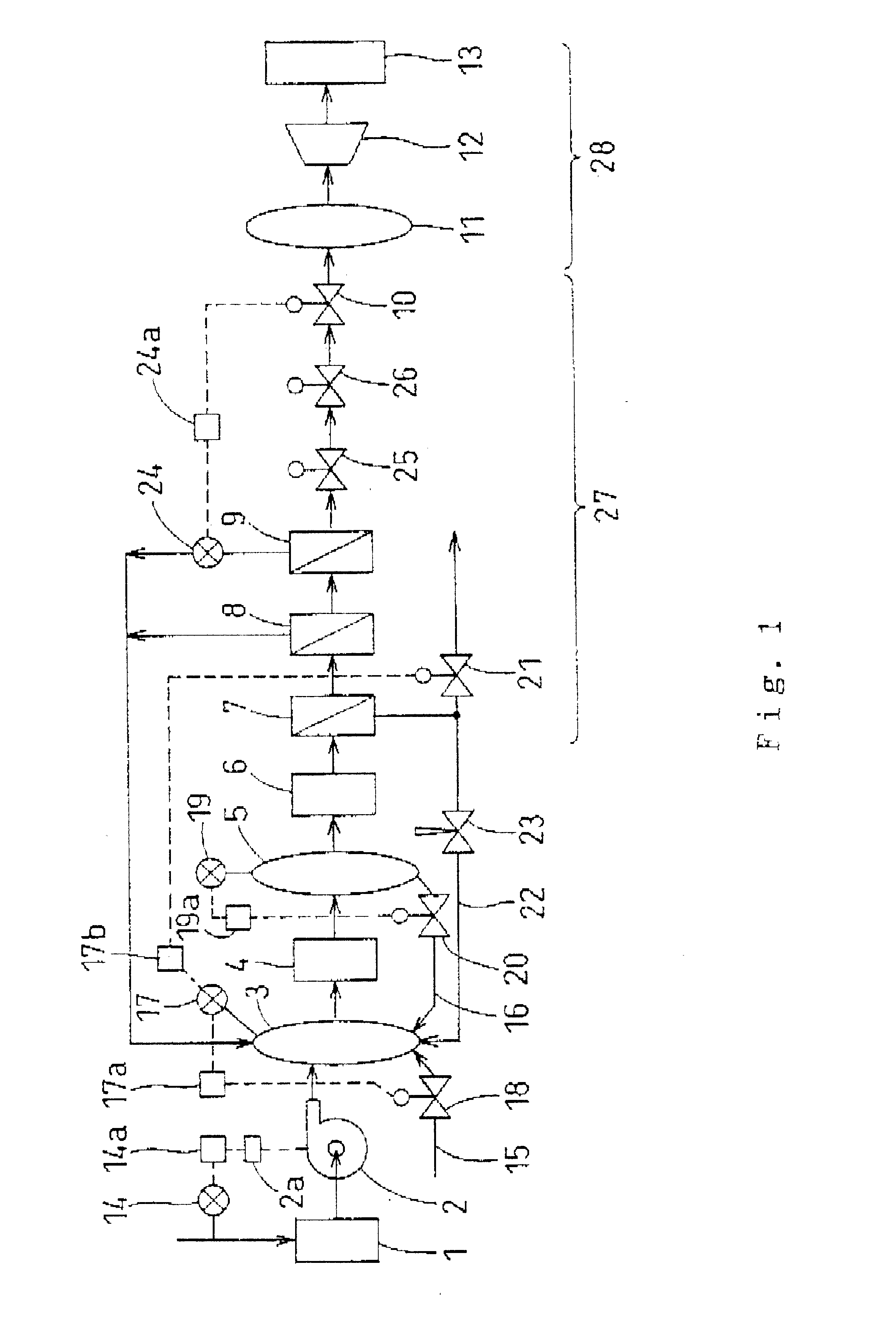
In other words, the perfluoro compound separation recovery method of the present invention includes the steps of detecting the pressure or flow rate of the other permeable gas flow; and controlling the flow rate of the other non-permeable gas flow so as to make the pressure or flow rate constant. Thus, even if there are fluctuations in the concentration of PFC gas in diluted mixed gas, the concentration of PFC gas after treatment can be kept roughly constant.
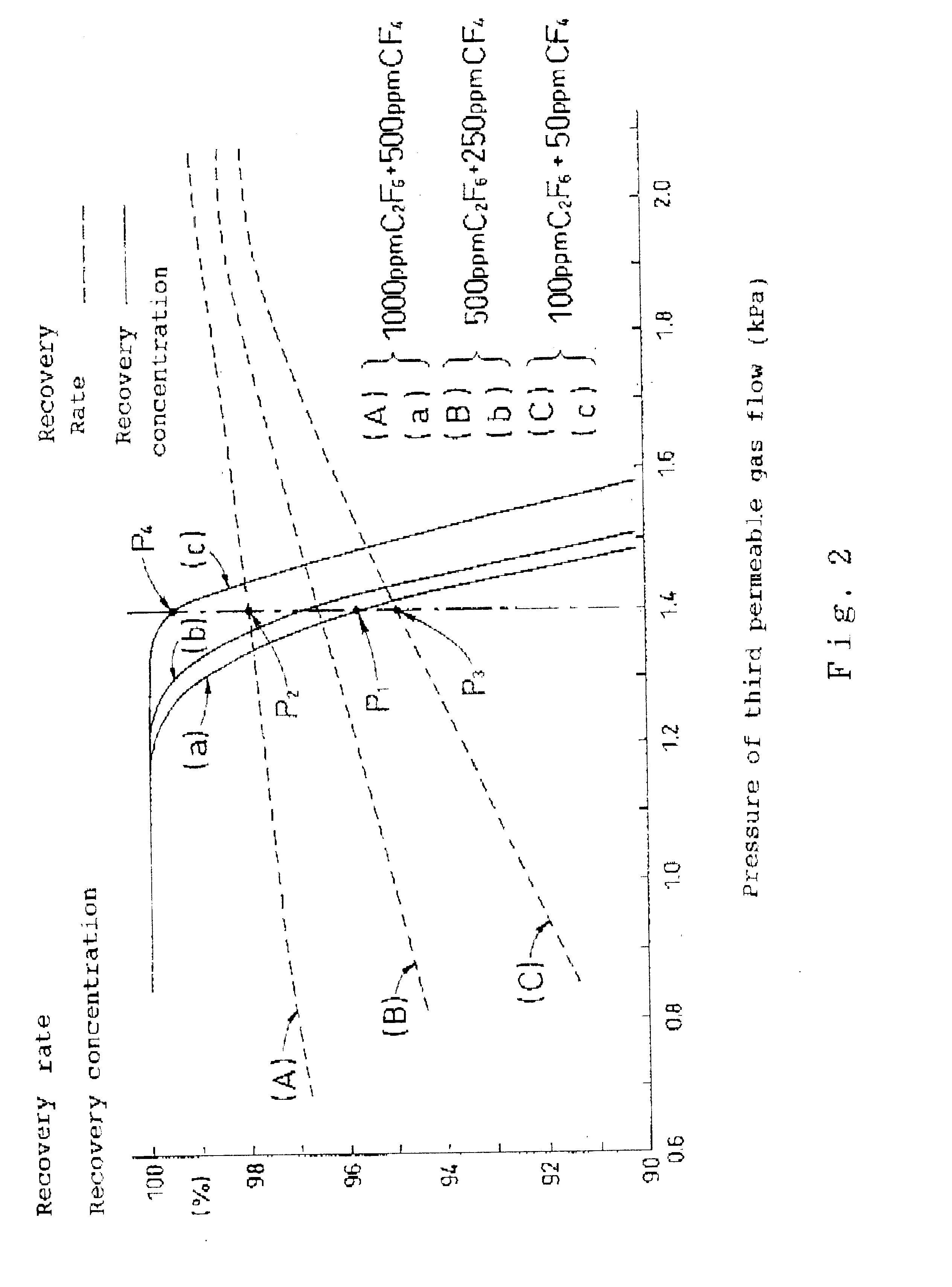
The first control valve 10 has a function to adjust the ratio between the amount of the third permeable gas flow and the amount of the third non-permeable gas flow, and this adjustment determines recovery rate and recovery concentration. In other words, when the first control valve 10 operates in a closing direction, resistance to the non-permeation side increases and recovering PFC gas flows to the permeation side. Accordingly, recovery rate decreases. However, as diluent gas which was flowing to the non-permeation side, also flows towards the permeation side, recovery concentration improves. To the contrary, when the first control valve 10 operates in an opening direction, resistance to the non-permeation side decreases and PFC gas, which was flowing to the permeation side, flows towards the non-permeation side. Accordingly, recovery rate improves. However, as diluent gas which was flowing to the permeation side, also flows to the non-permeation side, recovery concentration decreases.

Problems solved by technology

However, exhaust gas (diluted mixed gas) contains unreacted (undecomposed) PFC gas after use, causing such environmental problems as ozone layer depletion when the gas is released into the atmosphere.
However, in the conventional art mentioned above, the expensive concentration analyzer 53 is necessary to control the first control valve 10.
Moreover, since the concentration analyzer 53 requires time for concentration detection, the output thereof becomes inevitably intermittent.
It is also difficult to respond to periodic changes in the state of exhaust gas (exhaust timing of exhaust gas, flow amount of exhaust gas, concentration of PFC gas in exhaust gas, types of PFC gas in exhaust gas, and so forth).
Therefore, even if controlled to reach predetermined recovery concentration, it is essentially impossible to stabilize recovery concentration.
(1) Exhaust gas is diluted as outside air is taken in, so that the recovery efficiency of PFC declines.
As a result, it becomes difficult to control the internal pressure of the first tank 3 at a constant level.
However, as described above, it is difficult to set the internal pressure of the first tank 3 at a constant level due to a change in the state of exhaust gas.

Method used


Image

  • Method and apparatus for separating and recovering perfluoro compound
  • Method and apparatus for separating and recovering perfluoro compound
  • Method and apparatus for separating and recovering perfluoro compound

Examples


example 2

FIG. 5 shows pressure on the upstream side of the blower 2 (output of the first pressure sensor 14) and internal pressure on the upstream side (first tank 3) of the compressor 4 (output of the second pressure sensor 17) and internal pressure on the downstream side (second tank 5) of the compressor 4 (output of the third pressure sensor 19) when the flow rate of the exhaust gas flowing into a PFC separation recovery system was changed in the embodiment. FIG. 5 shows the output of the first to third pressure sensors 14, 17 and 19 when the set level of the second pressure sensor 17 was changed from -0.50 kPa to near atmospheric pressure.

It can be observed from FIG. 5 that the internal pressure of the first tank 3 (output of the second pressure sensor 17) is always roughly constant at a set level even when the flow rate of the exhaust gas changes. It also can be observed that a reset level is kept constant even after the set level of the second pressure sensor 17 is reset. Thus, since t...

example 3

The flow rate of the exhaust gas flowing into a PFC separation recovery system was changed in this embodiment, and FIG. 6 shows the output of the first to fourth pressure sensors 14, 17, 19 and 24 when the experiment was performed over a long period.

It can be observed from FIG. 6 that the output of the fourth pressure sensor 24 (pressure of the third permeable gas flow) can also be kept constant. Thus, it becomes possible to perform the PFC separation recovery method of the embodiment in which the fourth pressure sensor 24 is provided to the third permeable gas flow and the downstream thereof is connected to the first tank 3.


PUM

PropertyMeasurementUnit
pressureaaaaaaaaaa
pressureaaaaaaaaaa
pressureaaaaaaaaaa

Abstract

A PFC separation recovery method to separate and recover PFC by raising the pressure of diluted mixed gas consisting of PFC gas and diluent gas, and subsequently contacting the gas with a membrane which permeates more diluent gas than PFC gas, and to separate it into a permeable gas flow rich in diluent gas and a non-permeable gas flow rich in PFC gas; and a PFC separation recovery system therefor. Moreover, the method repeatedly separates the non-permeable gas flow into another permeable gas flow and another non-permeable gas flow by contacting the gas flow with another membrane having the same functions as those of the membrane; subsequently detecting the pressure or flow rate of the other permeable gas flow; and controlling the flow rate of the other non-permeable gas flow so as to make the pressure or flow rate constant.

Description

The present invention relates to a perfluoro compound separation recovery method to separate and recover a perfluoro compound with a membrane from diluted mixed gas in which the perfluoro compound is diluted, and a perfluoro compound separation recovery system therefor.Perfluoro compound (simply mentioned as "PFC" hereinafter) gas such as CF.sub.4, C.sub.2 F.sub.6, C.sub.3 F.sub.8, C.sub.4 F.sub.8, C.sub.4 F.sub.10, CHF.sub.3, SF.sub.6 and NF.sub.3 has been conventionally diluted with a large amount of N.sub.2 gas or the like for use such as in etching, cleaning a chamber and the like in the manufacturing process of semiconductors. Also, in the field of electrical machines, SF.sub.6 is similarly used as insulating gas.However, exhaust gas (diluted mixed gas) contains unreacted (undecomposed) PFC gas after use, causing such environmental problems as ozone layer depletion when the gas is released into the atmosphere.Thus, PFC gas in exhaust gas has been conventionally recovered. A PFC...

Claims


Application Information

Patent Timeline
Patent Type & Authority Patents(United States)
IPC IPC(8): B01D53/22C07C17/38C07C17/00
CPCB01D53/226C07C17/38C07C19/08B01D2257/204B01D2257/2066B01D2257/708Y02C20/30Y02P20/155Y02P20/151
Inventor KAWASAKI, FUMIOMATSUBAYASHI, ROSUKE
Owner DAIDO AIR PROD ELECTRONICS
Learn More