Thermal management system

a technology of management system and thermal management system, applied in the direction of transportation and packaging, light and heating equipment, laminated elements, etc., can solve the problems of system failure, and affecting the performance of the system

Inactive Publication Date: 2002-11-19
NEOGRAF SOLUTIONS LLC
View PDF14 Cites 355 Cited by
  • Summary
  • Abstract
  • Description
  • Claims
  • Application Information

AI Technical Summary

Problems solved by technology

However, microprocessors, integrated circuits and other sophisticated electronic components typically operate efficiently only under a certain range of threshold temperatures.
The excessive heat generated during operation of these components can not only harm their own performance, but can also degrade the performance and reliability of the overall system and can even cause system failure.
The increasingly wide range of environmental conditions, including temperature extremes, in which electronic systems are expected to operate, exacerbates these negative effects.
In many typical situations, heat transfer between the solid surface of the component and the air is the least efficient within the system, and the solid-air interface thus represents the greatest barrier for heat dissipation.
Limitations exist, however, with the use of copper heat sinks.
One limitation relates to copper's relative isotropy--that is, the tendency of a copper structure to distribute heat relatively evenly about the structure.
This can reduce the efficiency of heat dissipation using a copper heat sink.
In addition, the use of copper or aluminum heat sinks can present a problem because of the weight of the metal, particu

Method used


Image

  • Thermal management system
  • Thermal management system
  • Thermal management system

Examples


Embodiment Construction

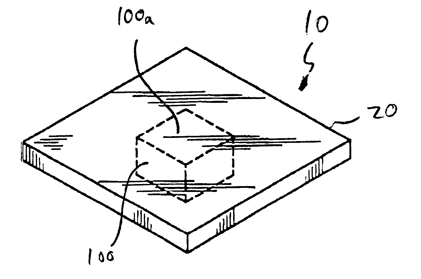
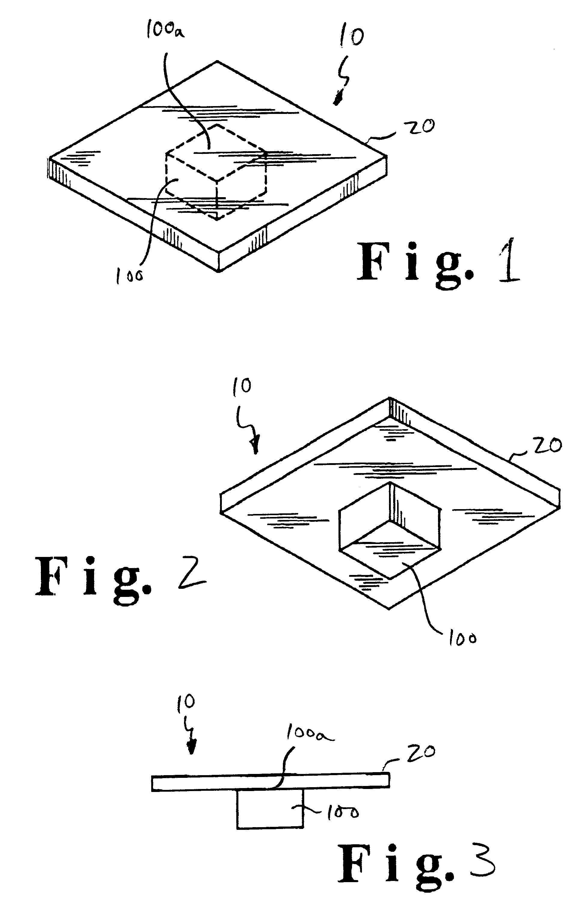
test apparatus was prepared, consisting of a heat source having an upper surface consisting of a generally flat surface of 1 / 2".times.1 / 4" in size, arrayed in a wind tunnel. Various embodiments of thermal management systems were installed on the heat source, with temperature measurements taken at Location A, adjacent the heat source / thermal management system interface and at Location B, on the thermal management system at a position farthest from the heat source (the lower the temperature reading at Locations A and B, the better the heat dissipation characteristics of the thermal management system being tested).

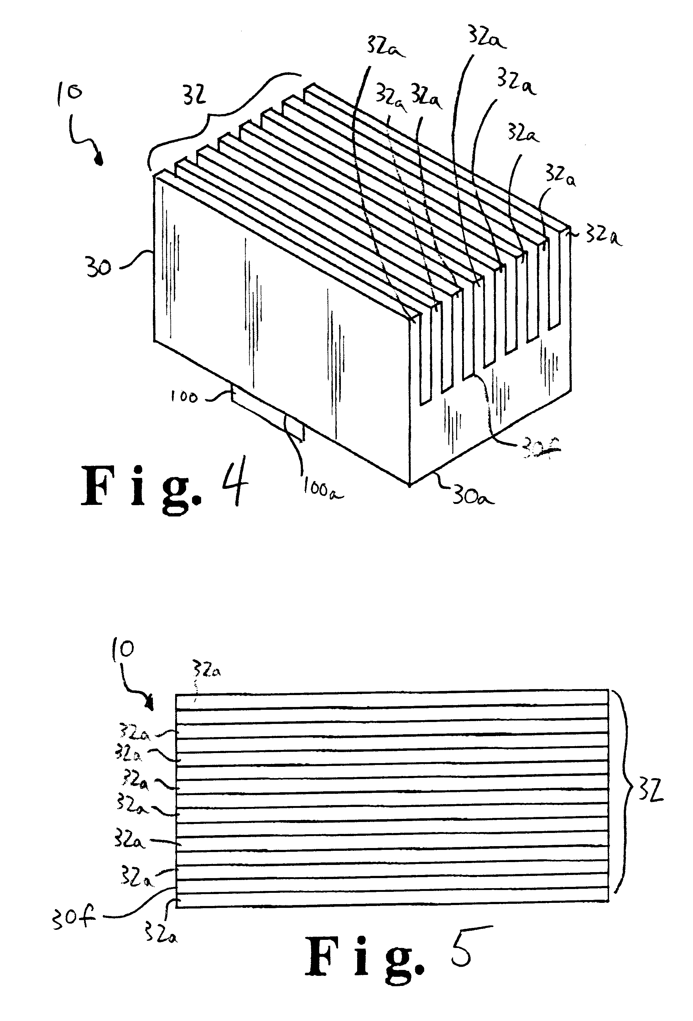
Run 1--a thermal management system consisting of a copper heat sink having dimensions of 1".times.1".times.0.8" and having 8 straight fins was arrayed on the heat source. A thermal interface consisting of a 1".times.1" sheet of anisotropic flexible graphite sheet was interposed between the copper heat sink and the heat source. The testing wind speed was 1.6 meters per second ...


PUM


Abstract

The present invention relates to a system for managing the heat from a heat source like an electronic component. More particularly, the present invention relates to a system effective for dissipating the heat generated by an electronic component using a thermal management system that includes a thermal interface formed from a flexible graphite sheet and/or a heat sink formed from a graphite article.

Description

The present invention relates to a system for managing the heat from a heat source like an electronic component. More particularly, the present invention relates to a system effective for dissipating the heat generated by an electronic component.BACKGROUND OF THE ARTWith the development of more and more sophisticated electronic components, including those capable of increasing processing speeds and higher frequencies, having smaller size and more complicated power requirements, and exhibiting other technological advances, such as microprocessors and integrated circuits in electronic and electrical components and systems as well as in other devices such as high power optical devices, relatively extreme temperatures can be generated. However, microprocessors, integrated circuits and other sophisticated electronic components typically operate efficiently only under a certain range of threshold temperatures. The excessive heat generated during operation of these components can not only ...

Claims


Application Information

Patent Timeline
IPC IPC(8): H01L21/02H01L21/48H01L23/34H01L23/373
CPCH01L21/4871H01L21/4882H01L23/373H01L23/3733Y10S165/905Y10T428/24273H01L2924/0002Y10S165/907Y10T428/30H01L2924/00F28F3/02F28F7/02F28F21/02
Inventor TZENG, JING WEN
Owner NEOGRAF SOLUTIONS LLC
Why Eureka
Try Eureka