Valve stem and method of manufacture; improved stem packing

a technology of stem packing and valve stem, which is applied in the field of valves, can solve the problems of reducing the smoothness of the valve stem that is necessary, causing leakage paths, and affecting the sealing performance of the stem packing, so as to enhance the performance of the improved valve stem, prevent leakage paths, and reduce the deterioration of the sealing surface of the stem packing.

Inactive Publication Date: 2002-12-03
T & R SOLUTIONS
View PDF35 Cites 11 Cited by
  • Summary
  • Abstract
  • Description
  • Claims
  • Application Information

AI Technical Summary

Benefits of technology

When the valve is new, the foregoing conditions are met and product inside the piping system is prevented from leaking to the outside. As the valve ages, chemical corrosion from the product, galvanic corrosion from the packing, and erosion and corrosion from atmospheric conditions all combine to reduce the smoothness of the valve stem that is necessary to maintain the seal. Also, roughness of the valve stem can occur as the valve stem is pulled through the stem packing during normal cycling due to abrasive materials accumulating between the valve stem and the seal. Any of these factors, and particularly combinations thereof, can result in leak paths being created and leakage to occur. This is unsatisfactory for numerous reasons, the most important of which involves increasing enforcement of the federal Clean Air Act which makes prevention of leakage or "fugitive emissions" essential.
While the prior art discloses a variety of valves, no prior disclosure shows a device where leakage is prevented by way of an overlay on the valve stem in the area of the stem packing. The improved valve stem of the present invention departs from the design of prior valve stems, and in doing so, provides a valve which prevents leakage and fugitive emissions as the valve ages.

Problems solved by technology

As the valve ages, chemical corrosion from the product, galvanic corrosion from the packing, and erosion and corrosion from atmospheric conditions all combine to reduce the smoothness of the valve stem that is necessary to maintain the seal.
Also, roughness of the valve stem can occur as the valve stem is pulled through the stem packing during normal cycling due to abrasive materials accumulating between the valve stem and the seal.
Any of these factors, and particularly combinations thereof, can result in leak paths being created and leakage to occur.
This is unsatisfactory for numerous reasons, the most important of which involves increasing enforcement of the federal Clean Air Act which makes prevention of leakage or "fugitive emissions" essential.
Previous attempts at solving the foregoing problems have included the application of the material sold under the trademark "HASTALLOY".RTM.. Such material is partially effective in slowing valve stem deterioration due to chemical attack but is ineffective as to mechanical degradation of the valve stem surface.
While the prior art discloses a variety of valves, no prior disclosure shows a device where leakage is prevented by way of an overlay on the valve stem in the area of the stem packing.

Method used


Image

  • Valve stem and method of manufacture; improved stem packing
  • Valve stem and method of manufacture; improved stem packing
  • Valve stem and method of manufacture; improved stem packing

Examples


Embodiment Construction

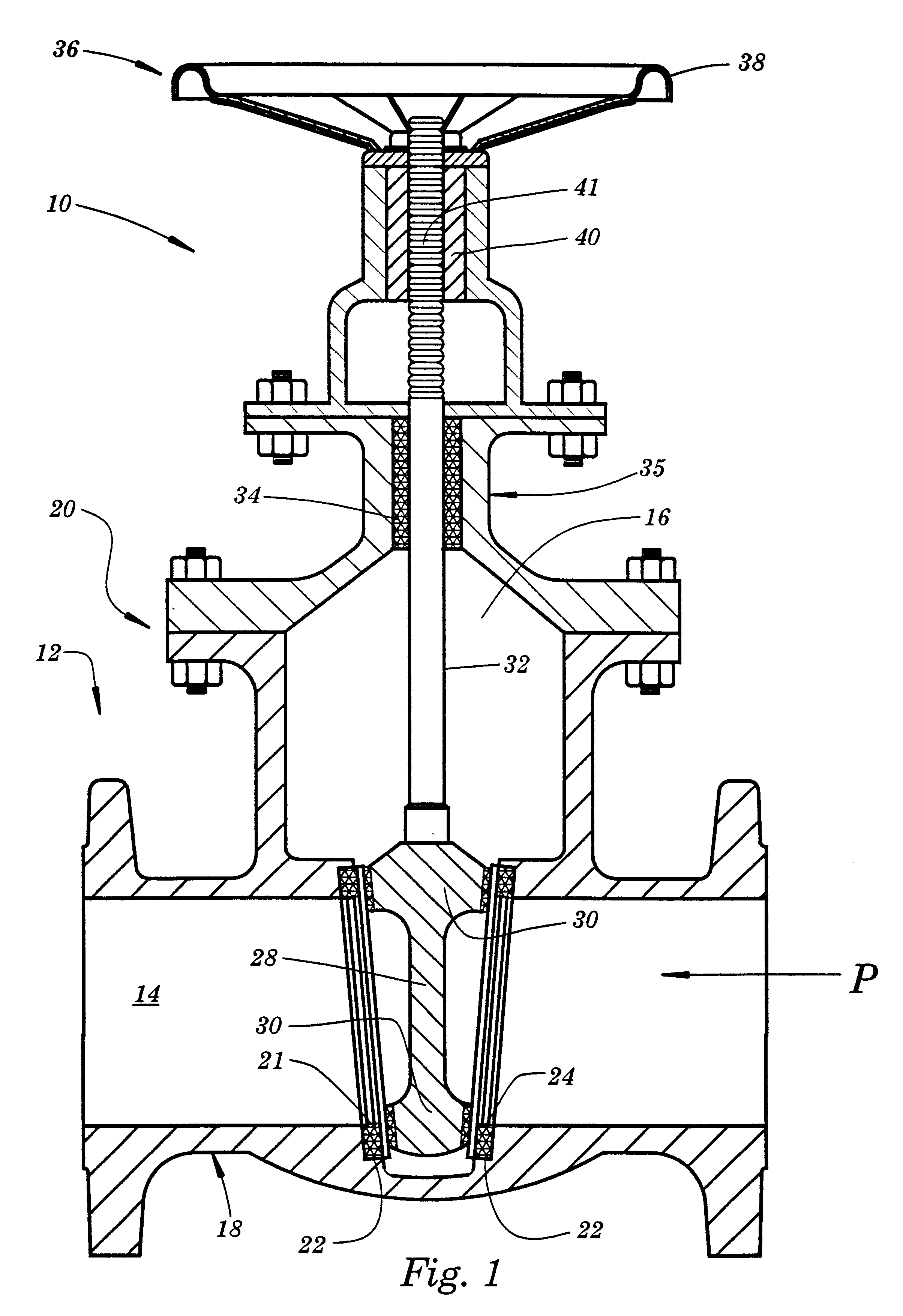
Referring now to the Drawings, and in particular to FIG. 1 thereof, there is shown an improved valve 10 having a body 12 constructed to provide a fluid path 14 and a body cavity 16. The fluid path 14 is generally located in the lower end 18 of body 12, while the cavity 16 extends from the upper end 20 of body 12 to the location of the fluid path 14. Disposed within the fluid path 14 are seat ring recesses 22 and seat rings 24 mounted in the seat ring recesses 22.

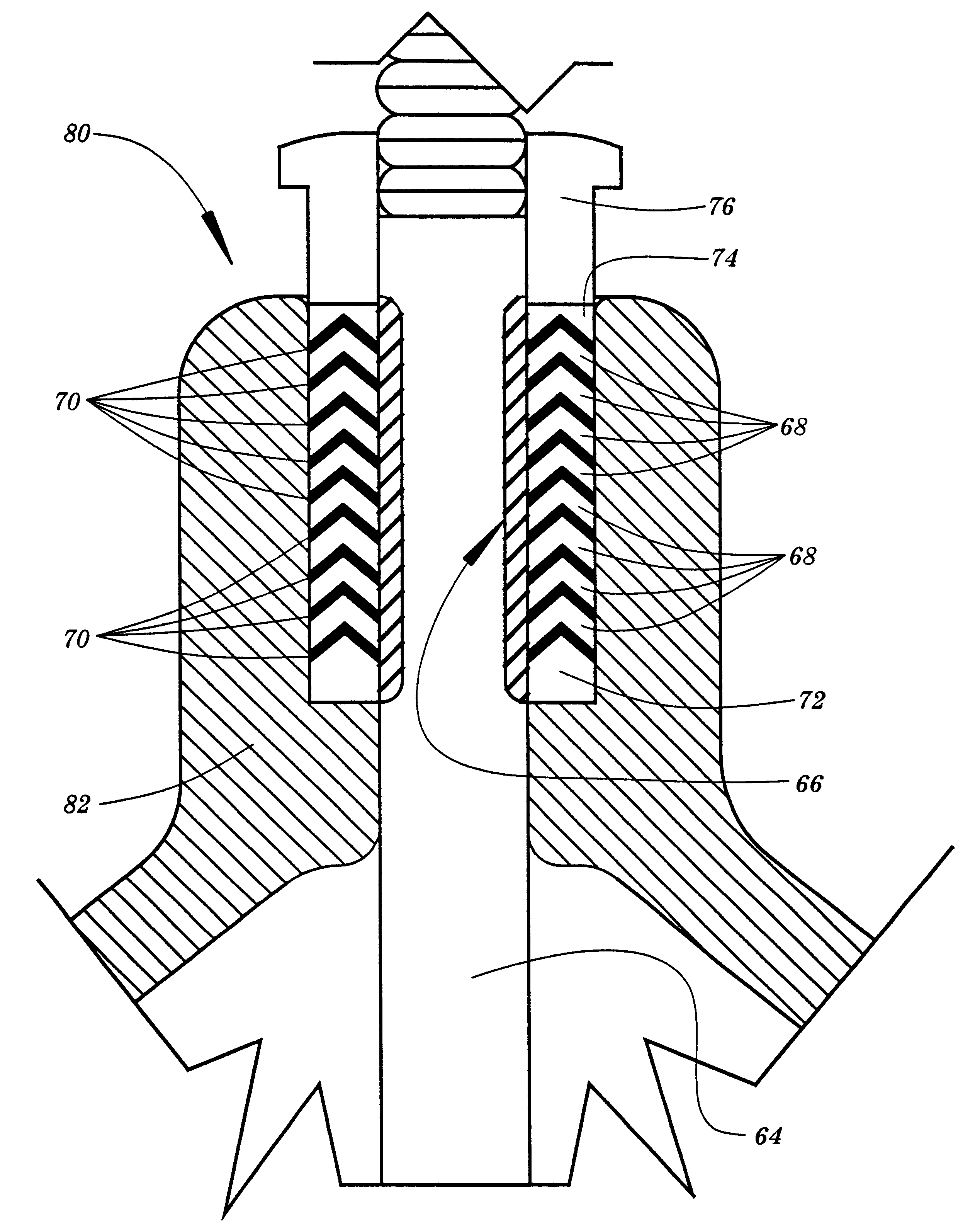
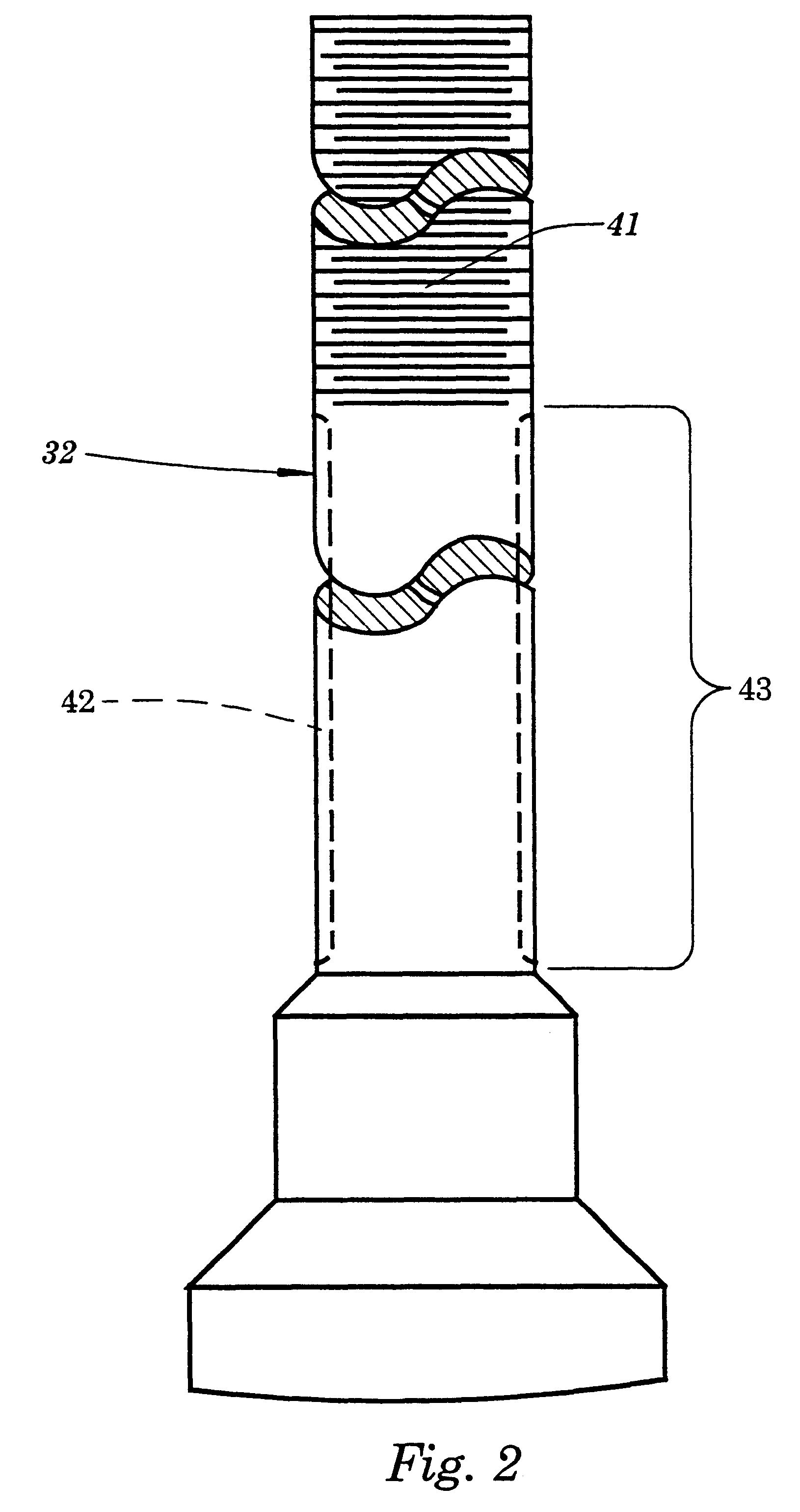
A valve member 28 is slidably positioned in the body 12 for movement through the cavity 16 such that sealing portions 30 of the valve member 28 may engage the seats 24. The valve member 28 is operably connected to a valve stem 32 which extends through a stem packing 34 located between the cavity 16 and a bonnet 35 mounted on the body 12.

The valve member 28 is actuated between the open and closed positions by an actuating member 36. The improved valve 10 is in the open position when the valve member does not engage the seats ...


PUM

PropertyMeasurementUnit
thicknessaaaaaaaaaa
thicknessaaaaaaaaaa
diameteraaaaaaaaaa

Abstract

A valve stem has a thickness of hardfaced material on its outer diameter in the area contacting the stem packing where the seal is formed which prevents corrosion, erosion and / or scratching of the valve stem, thereby preventing formation of leak paths. A valve packing comprises a vertically stacked array comprising alternating metal pressure rings and graphite seals.

Description

TECHNICAL FIELDThe present invention relates generally to valves of the type used in the petrochemical, refining, and other industries, and more particularly to an improved valve stem which is resistant to chemical and mechanical deterioration, to a method of manufacturing the valve stem, and to an improved packing construction useful in conjunction with the valve stem.BACKGROUND AND SUMMARY OF THE INVENTIONPerhaps the most common valves used in the petrochemical, refining, and other industries are gate valves. Major components of gate valves include a body, a valve stem, a sealing member, and seat rings which are engaged by the sealing member to close the valve. Because the valve stem must extend from inside the valve body to outside the body, a stem packing must be installed to effectively seal between the body and the valve stem, thereby containing the product inside the piping system of which the valve is a part. To achieve the necessary dynamic seal to both contain the product ...

Claims


Application Information

Patent Timeline
Patent Type & Authority Patents(United States)
IPC IPC(8): F16K3/12F16K3/02F16K27/04F16K41/02F16K41/00
CPCF16K3/12F16K27/047F16K41/02Y10T29/49425Y10T29/4941Y10T29/49982Y10S277/938Y10T137/4273Y10T137/6069Y10T137/6075
Inventor ROBERT, RAOUL W.
Owner T & R SOLUTIONS
Why Eureka
Try Eureka