Agitators for wave-making or mixing as for tanks, and pumps and filters

a technology of agitators and pumps, applied in the direction of mixing, rotary stirring mixers, transportation and packaging, etc., can solve the problems of increasing operating costs, reducing system performance, and most of the energy loss in a steady stream

Inactive Publication Date: 2002-12-03
SEAMAN ANTHONY E
View PDF59 Cites 68 Cited by
  • Summary
  • Abstract
  • Description
  • Claims
  • Application Information

AI Technical Summary

Problems solved by technology

Most of the energy losses in a steady stream occur at the boundaries of the flow.
The dissipation of energy in large volumes of fluid, whether from a wave or a stream, causes turbulence.
This, in turn, causes a decrease in system performance and an increase in operating costs.
The main drawback to these pumps is the weak coupling between the magnets.
The magnetic coupling cannot transfer motor torque to the impeller efficiently.
Small changes in motor speed, from minor voltage fluctuations causes significant changes in the pump output.
While this type of pump recirculates water and low viscosity fluids without any problem, it has little value for high viscosity fluids.
For the work

Method used


Image

  • Agitators for wave-making or mixing as for tanks, and pumps and filters
  • Agitators for wave-making or mixing as for tanks, and pumps and filters
  • Agitators for wave-making or mixing as for tanks, and pumps and filters

Examples


Embodiment Construction

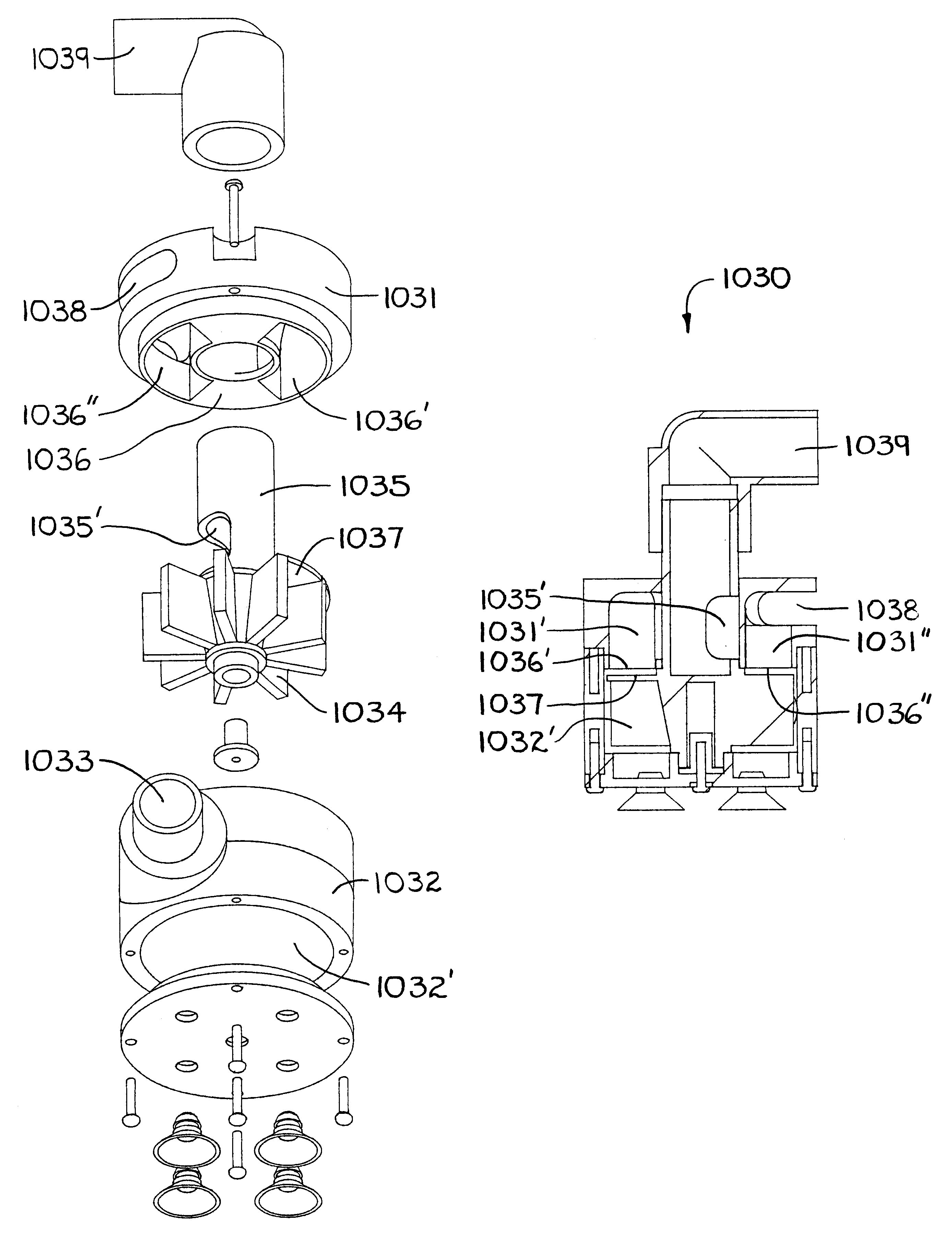
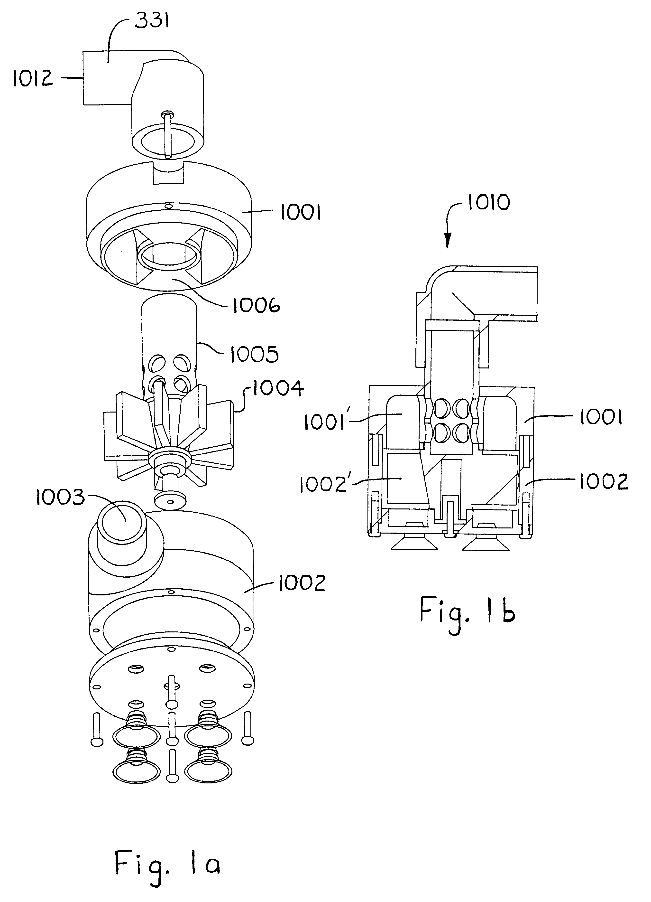
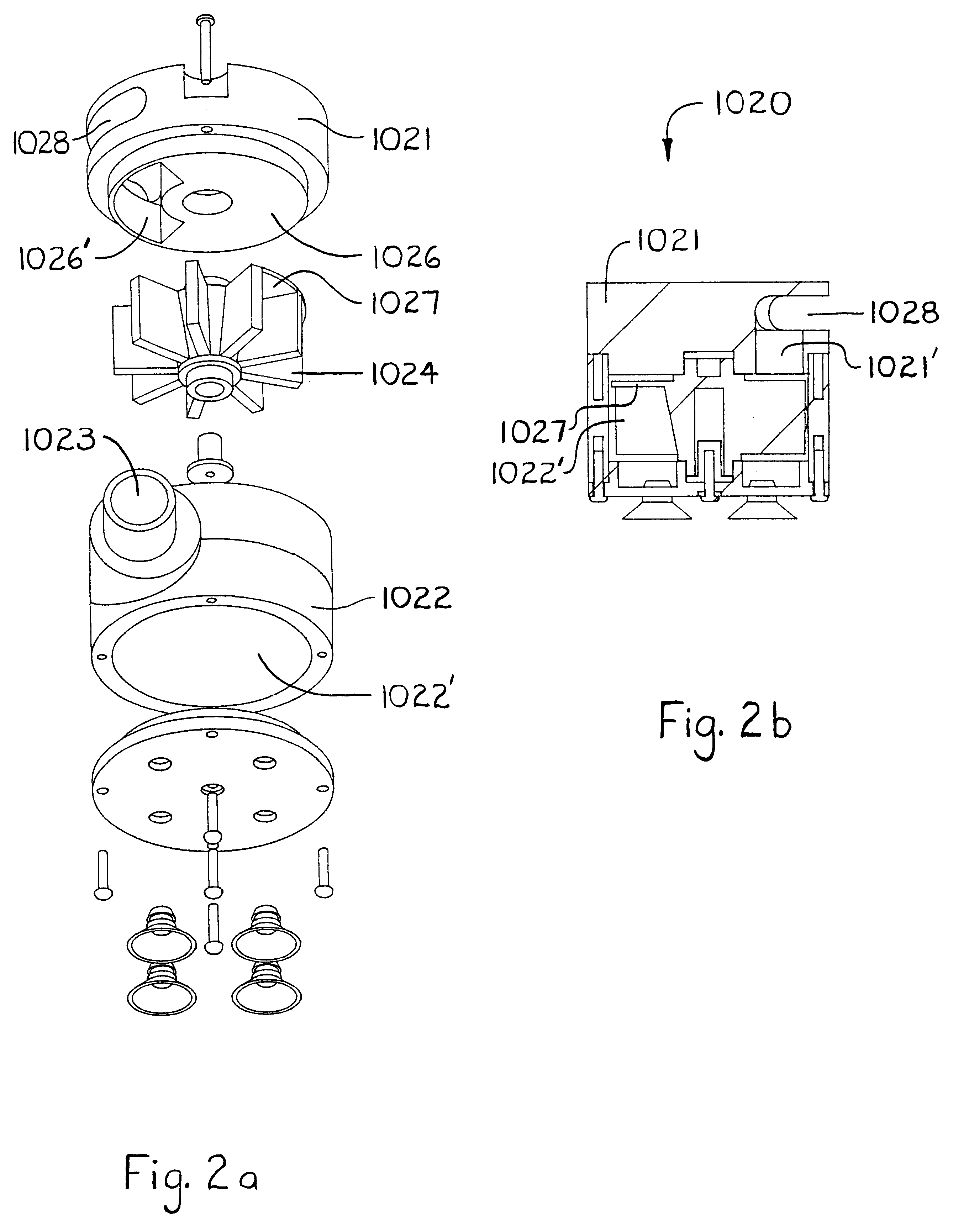
FIGS. 1a and 1b show a rotator 1010 in accordance with the invention. The rotator 1010 includes upper and lower housings 1001 and 1002 which respectively define upper and lower plenums 1001' and 1002'. The lower housing encloses the turbine 1004, which is driven at constant speed by the steady infeed flow entering through the inlet 1003. The turbine 1004 has appended to it a hollow apertured shaft 1005 which extends through the partition wall 1006 between the upper and lower plenums, to couple to a 90.degree.-nozzle forming the discharge port 1012 for this rotator 1010. The 90.degree. discharge port 1012 protrudes out above a top wall of the upper housing 1001. The flowthrough of the infeed stream in the inlet 1003 causes the turbine 1004 to spin. The spinning turbine 1004 spins the directly coupled 90.degree. discharge port 1012 through complete rotations. The infeed stream flows up out of the vanes of the turbine 1004, into the upper plenum 1001', into the lumen of the hollow shaf...


PUM


Abstract

A tank agitator connects to a low head feed and causes agitation by discharging through a port that might rotate, oscillate, or otherwise issue a pulsing stream. This agitator has a housing with a turbine plenum and an exhaust plenum. A turbine in the turbine plenum spins by the flowthrough of the feedwater and exhausts to the exhaust plenum. A hollow drive shaft is spun by the turbine and extends through the exhaust plenum and to terminate outside the housing. It has an aperture that allows water in the exhaust plenum to flow into its lumen. A nozzle caps the shaft and is bent such that the discharge issuing therefrom sweeps in circles with the spinning of the drive shaft. A variant form of the agitator includes a drive train that incorporates a drag link to convert the spinning input of the turbine into an oscillating output in the drive shaft. In another variant form, the discharge is pulsed. To do this, the exhaust plenum lies between an opening to the turbine plenum and a port in the housing wall to the outside. A blocker door is coupled to and driven by the spinning turbine to cycle between uncovering and covering one of the exhaust opening and the discharge port. Given the foregoing, the discharge stream issuing from the discharge port will pulse between alternating phases of flow and quiescence.

Description

1. Field of the InventionThe invention relates to agitators or circulators for inducing currents--or waves if that is preferred--in a given tank. One example illustrative use environment for the invention involves salt water aquariums in which it is desirable to generate a wave and / or current environment similar to an actual reef so that filter-feeding organisms like coral are given plenty of plankton circulated by them to feed on. Other example use environments include without limitation process industries like the chemical, food, or water treatment industries and so on, for use in mixing tanks to mix dissolving chemicals or blend fluids or the like, including suspending or dispersing particles, bubbles, droplets, fluid clumps and so on.Additional aspects and objects of the invention will be apparent in connection with the discussion further below of preferred embodiments and examples.2. Prior ArtWaves at the surface of fluids appear as a variation of the familiar sine curve in mat...

Claims


Application Information

Patent Timeline
IPC IPC(8): B01F5/02B01F5/00B01F5/10
CPCB01F5/0218B01F5/0225B01F5/0231B01F5/0243B01F5/10Y10S239/01A01K63/047B01F25/212B01F25/2121B01F25/2122B01F25/2124B01F25/50
Inventor SEAMAN, ANTHONY E.
Owner SEAMAN ANTHONY E
Why Eureka
Try Eureka