Resonant power converter with primary-side tuning and zero-current switching

a power conversion and primary-side tuning technology, applied in process and machine control, electric variable regulation, instruments, etc., can solve problems such as ringing, circuit parasitic bounded, and inability to achieve ringing,

Inactive Publication Date: 2002-12-03
FIGUEROA SALVADOR
View PDF10 Cites 48 Cited by
  • Summary
  • Abstract
  • Description
  • Claims
  • Application Information

AI Technical Summary

Problems solved by technology

While the variable resistance yields a low noise characteristic at the output terminals, objection is based on inefficient power transfer.
Thus, input power is described in terms of duty cycle: Pin (pk) D. The principal drawback to this type of power conversion lies in the fact that switching action interrupts input current converting it into a train of discontinuous pulses.
Interruption of power current leads to circuit parasitics being bounded by a broadband fre...

Method used


Image

  • Resonant power converter with primary-side tuning and zero-current switching
  • Resonant power converter with primary-side tuning and zero-current switching
  • Resonant power converter with primary-side tuning and zero-current switching

Examples


first embodiment

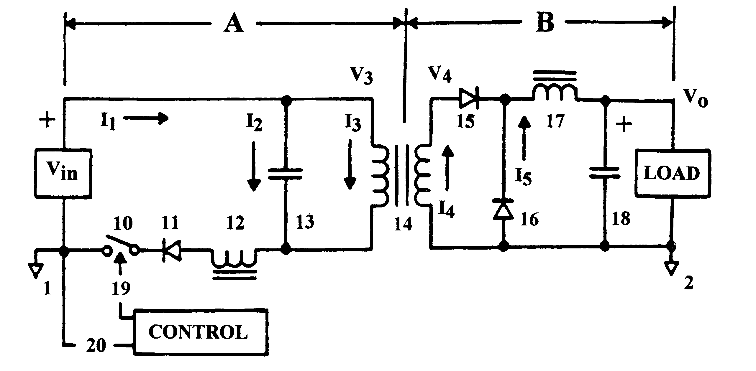
Following description of circuit operation refers to the first embodiment based on a design coefficient K of 1.41. Referring to FIG. 3, successive closure of power switch 10 establishes a state of equilibrium in functional loop--A allowing power switch 10 transitional states to migrate to their natural time-domain. This juncture, within the prescribed time base, is coincident with the amplitude of the average volt-second product enclosed in the Fn portion of the cycle for the on-time transition as a fixed event. The off-time transition, being a design variable, is set to occur at some point beyond the cross-over threshold of the average volt-second amplitude for the forced oscillation, Fo, period of the decaying voltage across resonating capacitor 13, but before it decays below the projected level of DC voltage source Vin. Power switch 10 turn-off in this region insures zero-current switch transition and prevents inadvertent turn-on of unidirectional conducting device 11 which commu...

second embodiment

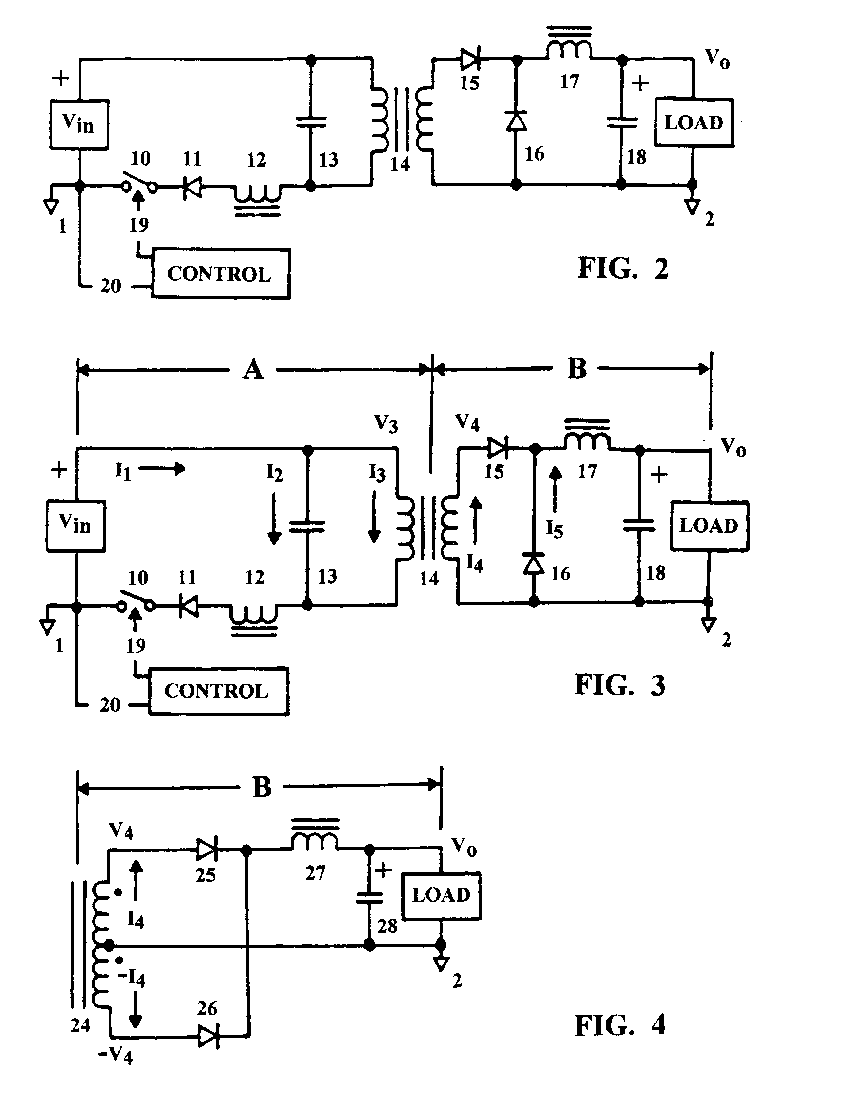
The following description of circuit operation refers to the second embodiment based on a design coefficient K of 1.41. Circuit structure is that of transformer in FIG. 3 terminated by a center-tapped secondary winding as shown in FIG. 4. This configuration allows full-wave power transfer from the DC voltage source Vin to the output load during each half cycle of the composite carrier-frequency. Input functional loop--A, as described for FIG. 3 in previous design examples, establishes an AC voltage signal applied by resonant capacitor 13 to the input winding of transformer 24 which is identical to that of transformer 14. The secondary winding on transformer 24 is center-tapped as shown in FIG. 4 and routed to a full-wave rectifier / filter assembly for extraction of the DC component applied to a DC load. The operating region for a design coefficient K of 1.41 is defined as point--A in FIG. 5. Internal phasing of transformer 24 output winding in FIG. 4, is such that the voltage applied...


PUM


Abstract

A DC power converter consisting of a series-resonant branch used to transform a DC voltage source into a DC current source exhibiting, a uni-polar, zero-current-switching characteristic. Frequency of the series-resonant branch, acting in concert with reflected load parameters, provides a forced oscillation frequency, Fo, component to an AC voltage source generated across the input winding of a power transformer by the resonant capacitor. Complex load parameters allow AC input current, displaced by 90° from the AC voltage source, to flow in the transformer primary winding throughout a composite, carrier-frequency cycle. Another component of the carrier-frequency consists of a resonant, natural oscillation frequency, Fn, resulting from resonance by the AC voltage source capacitance with the open-circuit inductance of the primary winding on the input power transformer. The composite carrier-frequency, Fo+Fn, transported through the input power transformer is directed to a rectifier/filter assembly and applied as a DC voltage to an output load. Thus, the uni-polar DC series-resonant branch is converted into an AC power transfer function, fully isolated from the input power switch, by the AC voltage source capacitor. The power transfer function characterizing a bi-polar power inverter requires a single power switch referenced to the input power return bus.

Description

1. Field of the InventionThis invention relates to a zero-current switching DC power conversion process. And more specifically, resonant power converters using a series-resonant input stage to source AC voltage to an input power transformer via energy storage in the series-resonant capacitor. Wherein a compound frequency consisting of a forced sine wave oscillating frequency, Fo, couples to a resonant sine wave oscillating at its natural frequency, Fn. The two components combine to synthesize a composite, sine wave carrier-frequency providing a uni-polar and / or a bi-polar power supply transfer function to the power transmission loop.2. Description of Prior ArtSundry methods exist for converting an input level of DC power to another level for delivery to a prescribed load. Two conventional design methodologies in popular practice are generally classified as either: linear or switching mode. In view that either finds acceptance in certain application requirements neither enjoys the br...

Claims


Application Information

Patent Timeline
IPC IPC(8): H02M3/24H02M3/335
CPCH02M3/335H02M3/33507Y02B70/1433Y02B70/10
Inventor FIGUEROA, SALVADOR
Owner FIGUEROA SALVADOR
Why Eureka
Try Eureka