Self-diagnostic circuitry for emergency lighting fixtures

a self-diagnostic circuit and emergency lighting technology, applied in the field can solve the problems of failure detection failure of testing procedures, and inability to detect the failure of emergency lighting systems, and achieve the effect of low power and low cos

Inactive Publication Date: 2002-12-31
ABL IP HLDG
View PDF17 Cites 130 Cited by
  • Summary
  • Abstract
  • Description
  • Claims
  • Application Information

AI Technical Summary

Benefits of technology

It is a further object of the invention to provide self-test/self-diagnostic emergency lighting fixtures configured in a low power, low cost circuit board with contr

Problems solved by technology

Loss of line voltage results in the switching of the emergency ballast to power the lamping of the emergency lighting system through the emergency power supply, power being typically provided to the lamping for operation of the emergency lighting system for a relatively short period of time.
Neglect of testing procedures often occurs and results in detection of the failure of the emergency lighting system only when an em

Method used


Image

  • Self-diagnostic circuitry for emergency lighting fixtures
  • Self-diagnostic circuitry for emergency lighting fixtures
  • Self-diagnostic circuitry for emergency lighting fixtures

Examples


first embodiment

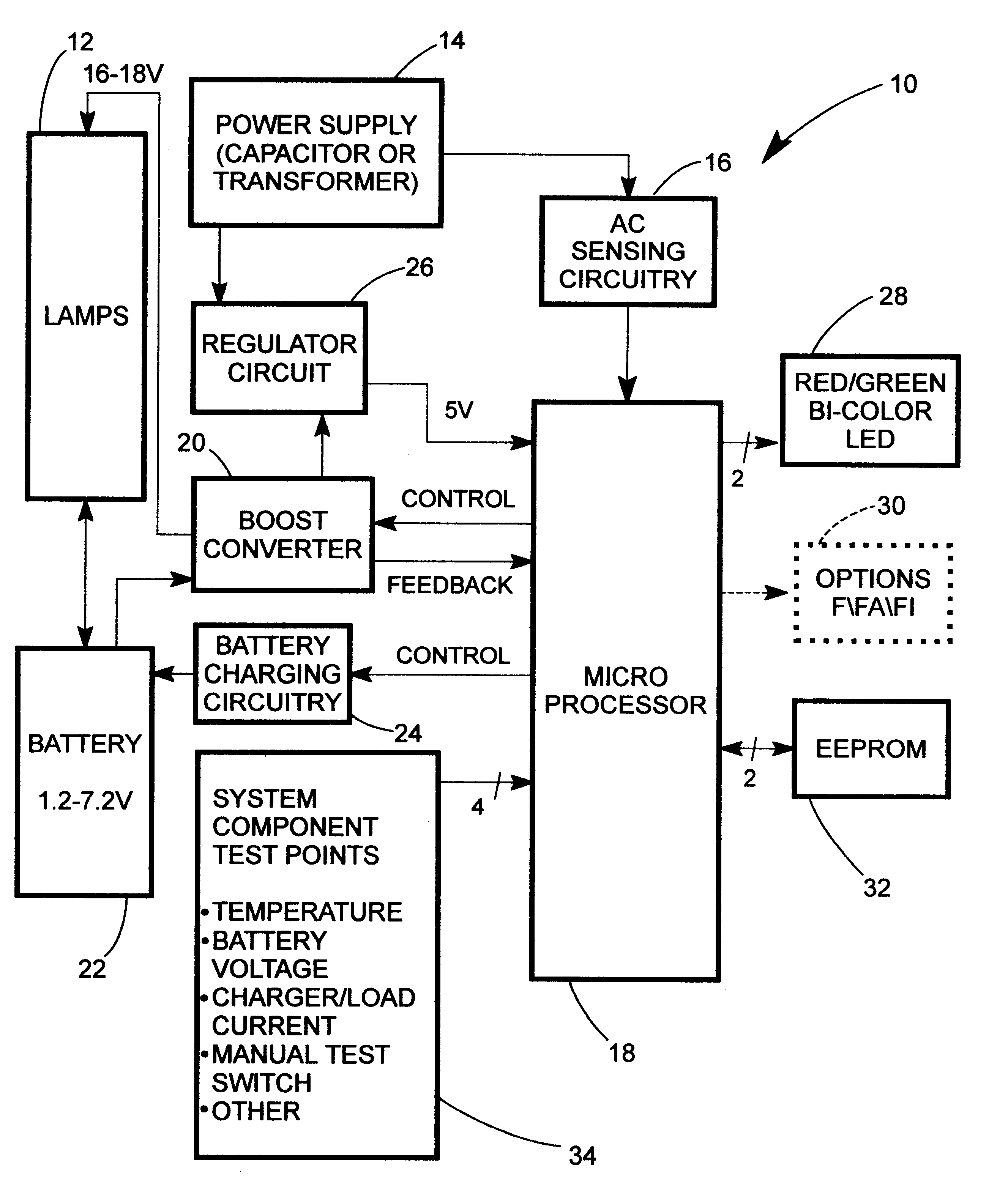
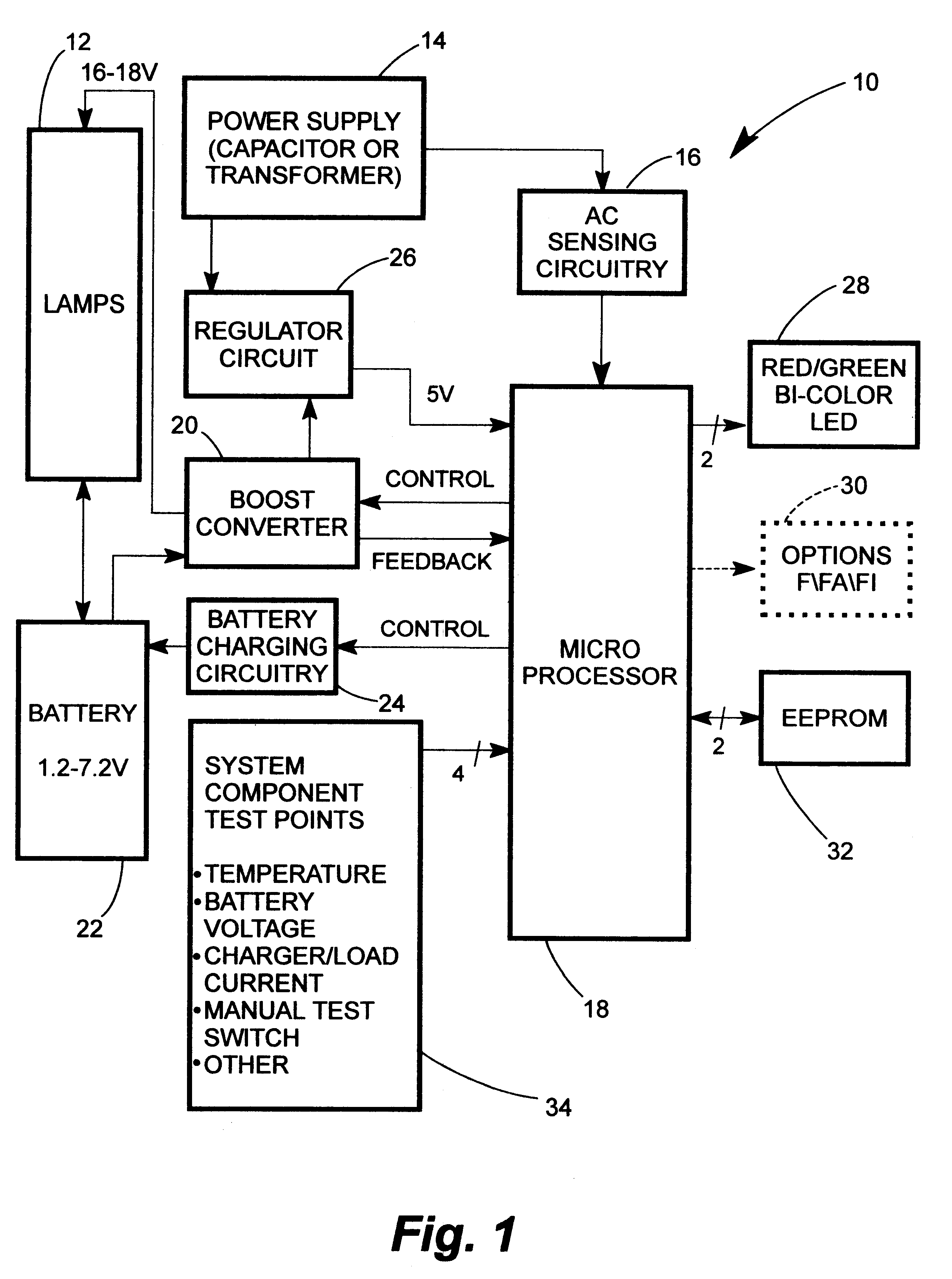
Referring now to the drawings, FIGS. 1 through 3 illustrate the invention as comprising an emergency lighting system seen generally at 10. In the system 10, lamping 12 preferably takes the form of an array of light emitting diodes arranged in series. The lamping 12 is operated under normal, non-emergency conditions through the power supply 14 which includes normal line voltage circuitry 16 for sensing the presence of AC line voltage being fed to the lamping 12 as an input signal fed to the circuitry 16 from the power supply 14, the circuitry 16 then feeding a signal to microprocessor 18. The microprocessor 18 controls boost converter 20 to supply power of reduced current to the lamping 12 on discontinuation of line voltage, voltage being supplied to the boost converter by means of battery 22. The microprocessor 18 also controls battery charging circuit 24 which shuts down on control by the microprocessor 18. The power supply 14 supplies power to regulator circuit 26 which supplies p...

second embodiment

Considering now the invention as is particularly shown in FIG. 5, it is to be noted that the differences between the circuitry of FIG. 5 and FIG. 3 are related as has been described hereinabove to basic load and battery chemistry considerations as exist between emergency exit signage utilizing light emitting diodes, requiring the circuitry of FIG. 3, and emergency unit equipment utilizing incandescent lamping, requiring the circuitry of FIG. 5. In the circuitry of FIG. 3, nickel / cadmium batteries are utilized as the emergency power source while lead-acid batteries are utilized with the circuitry of FIG. 5.

Much of the circuitry of FIG. 3 is incorporated into the circuitry of FIG. 5, particularly the microprocessor 18 and the EEPROM 32. Further, reset circuitry 120 is essentially identical as are the crystal clock 106 and the connector 108. D.C. local filtering at 152 is produced in a similar fashion and the pull-up resistors operate in a similar manner. The difference amplification f...


PUM


Abstract

Electronic self-test and/or self-diagnostic systems particularly useful with emergency lighting fixtures, including exit signage having light emitting diodes as light sources and unit emergency fixtures powered with lead-acid batteries, the systems perform testing and diagnostic functions on the circuitry, power supply, charger and lamping of such fixtures either by manual or automatic initiation. Testing functions are provided through use of a programmable microprocessor, the diagnostic circuitry not only monitoring operation of charger/transfer circuitry but also controlling the charger/transfer circuitry to enable alternate strategies for alleviation of a given failure. In emergency mode of a light emitting diode exit sign, a microprocessor-controlled two-stage inverter is employed not only to power the LED light source, but also to efficiently power the microprocessor. Power to the microprocessor is controlled by the microprocessor itself and can therefore be discontinued after appropriate operation until mains power is restored, thereby effectively reducing power consumption to zero. System operation can be flexibly configured through use of a two-wire serial link between modular elements of the system. Incandescent emergency unit fixtures due to high drain rates and output loads require emergency mode operation through use of lead-acid batteries, thereby requiring voltage controlled charging and relay transfer, the self-test and/or self-diagnostic circuitry of the invention used with emergency unit fixtures thus differing in various respects from the circuitry employed for the LED exit signage fixtures and primarily in the need to measure both charge and discharge currents, the circuitry having a larger dynamic range in addition to a capability of measuring both positive and negative currents.

Description

1. Field of the InventionThe invention relates generally to emergency lighting systems normally operable from a mains power supply and configured to operate from an emergency power source on failure of mains power, the invention particularly relating to programmable self-test and / or self-diagnostic systems for emergency lighting fixtures and which are capable of manual or automatic performance of testing and diagnostic functions on the circuitry, power supply, charging system and lamping thereof.2. Description of the Prior ArtEmergency lighting systems have become ubiquitous due to code requirements, power typically being provided to emergency lighting systems under normal operating conditions by mains power supplied both to a normal AC ballast for light generation and to an emergency ballast for maintaining a charge on a power supply typically carried by the emergency lighting system, the power supply usually taking the form of an internal battery. Loss of line voltage results in t...

Claims


Application Information

Patent Timeline
IPC IPC(8): G01R31/00G01R31/28G01R31/36G06F19/00H02J9/02H02J9/00H02J7/00
CPCH02J7/0029H02J7/0065H02J9/005H02J9/02H05B33/0815H05B33/0893H05B39/044H05B45/58H02J2207/20Y02B20/00Y04S20/20Y02B70/30H05B45/38H05B45/382H02M7/05
Inventor LANE, JOHN EVANFARTHING, RICHARD C.
Owner ABL IP HLDG
Why Eureka
Try Eureka