High-voltage feedthrough capacitor

a high-voltage feed-through capacitor and capacitor technology, applied in the direction of feed-through capacitors, fixed capacitor details, transit-tube leading-in arrangements, etc., can solve the problems of voltage feed-through capacitor and cannot be increased, the area of the electrodes is influenced by the shape, and it is difficult to secure a high capacitan

Inactive Publication Date: 2003-01-21
TDK CORPARATION
View PDF11 Cites 77 Cited by
  • Summary
  • Abstract
  • Description
  • Claims
  • Application Information

AI Technical Summary

Benefits of technology

It is another object of the present invention to provide a high-voltage feedthrough capacitor which is capable of securing a high capacitance irrespective of the shape thereof as a whole.
It is still another object of the present invention to provide a high-voltage feedthrough capacitor which has a high capacitance and is capable of improving filter properties, while securing moldability.
It is further object of the present invention to provide a high-voltage feedthrough capacitor in which resin materials having different functions can be used in such different ways that a high-permittivity resin is used as a capacitor part and a resin suitable for armoring is used as an armoring insulator.
In the high-voltage feedthrough capacitor of the present invention, the two feedthrough capacitors extend through the respective through-holes formed in the grounding member and are fitted to the grounding member, while the armoring insulator covers the peripheries of the feedthrough capacitors and the periphery of the grounding member. According to this structure, the high-voltage feedthrough capacitor in which both feedthrough capacitors are connected to a magnetron for an microwave oven can be used as a filter capacitor for the prevention of undesired radiation noise. In addition, the high-voltage feedthrough capacitor can have excellent electrical insulating properties and excellent moisture resistance.
The feedthrough capacitors each has been fitted to the grounding member, while the armoring insulator covers the peripheries of the feedthrough capacitors and the periphery of the grounding member. According to this structure, a material which has excellent moldability and is different from the material of the dielectric layer as a component of each feedthrough capacitor can be used to form the armoring insulator so as to cover the peripheries of the feedthrough capacitors and the periphery of the grounding member therewith. Consequently, a high capacitance can be obtained without sacrificing moldability, whereby a high-voltage feedthrough capacitor having excellent filter properties can be obtained.

Problems solved by technology

One problem of the conventional one described above is that since the pair of electrodes, which generate a capacitance, are constituted of a part of the grounding plate and a part of the central conductor, the area of the electrodes is influenced by the shape of the high-voltage feedthrough capacitor and cannot be increased.
It has hence been difficult to secure a high capacitance by increasing the area of the electrodes and to obtain improved filter properties.
Another problem is that, if a high-permittivity material is incorporated into the thermosetting resin to be used for constituting the dielectric member between the electrodes in order to increase the permittivity of the dielectric member, the resultant thermosetting resin has impaired moldability, resulting in a reduced yield.
This means that there is a limitation on obtaining an increased capacitance and thus improving filter properties, while securing moldability.
Still another problem is that since the dielectric member disposed between the electrodes serves also as a filler, it is impossible to use two resin materials having different functions in such different ways that a high-permittivity resin is used as a capacitor part and a resin having an ordinary permittivity is used as a filler.
It is therefore difficult to optimize the two functions.

Method used


Image

  • High-voltage feedthrough capacitor
  • High-voltage feedthrough capacitor
  • High-voltage feedthrough capacitor

Examples


Embodiment Construction

Preferred embodiment according to the present invention will be described as follows referring to the accompanying drawings.

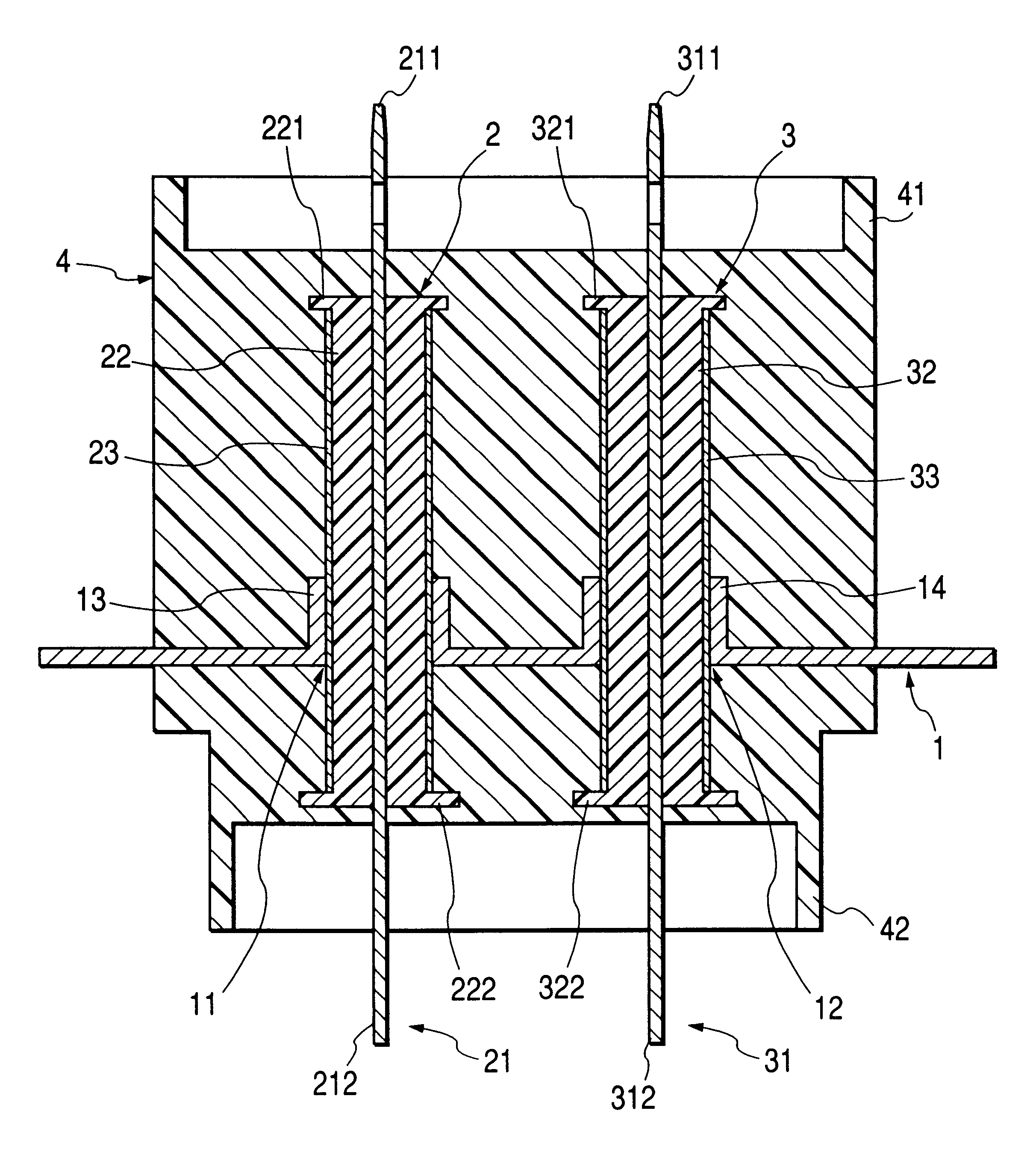
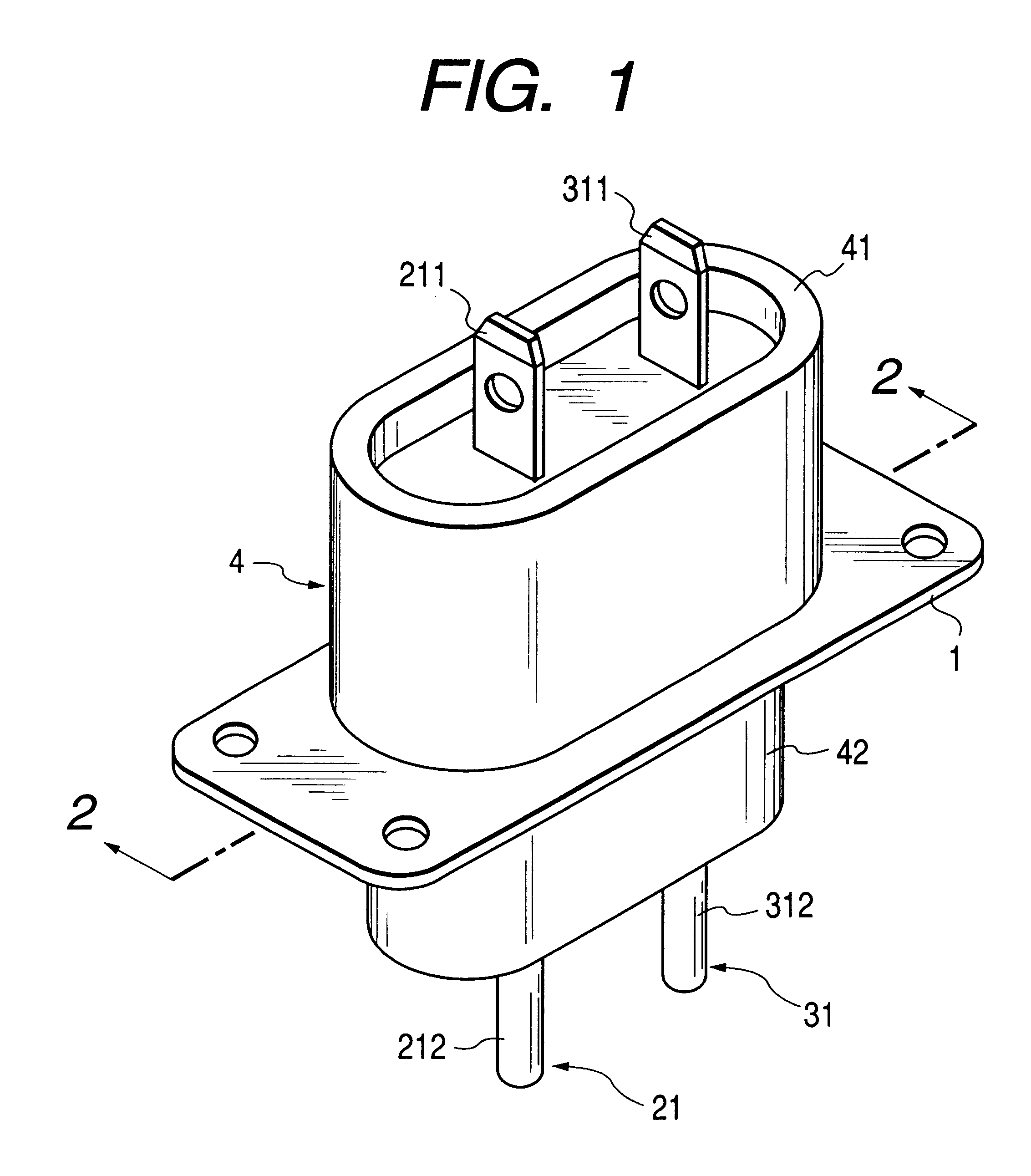
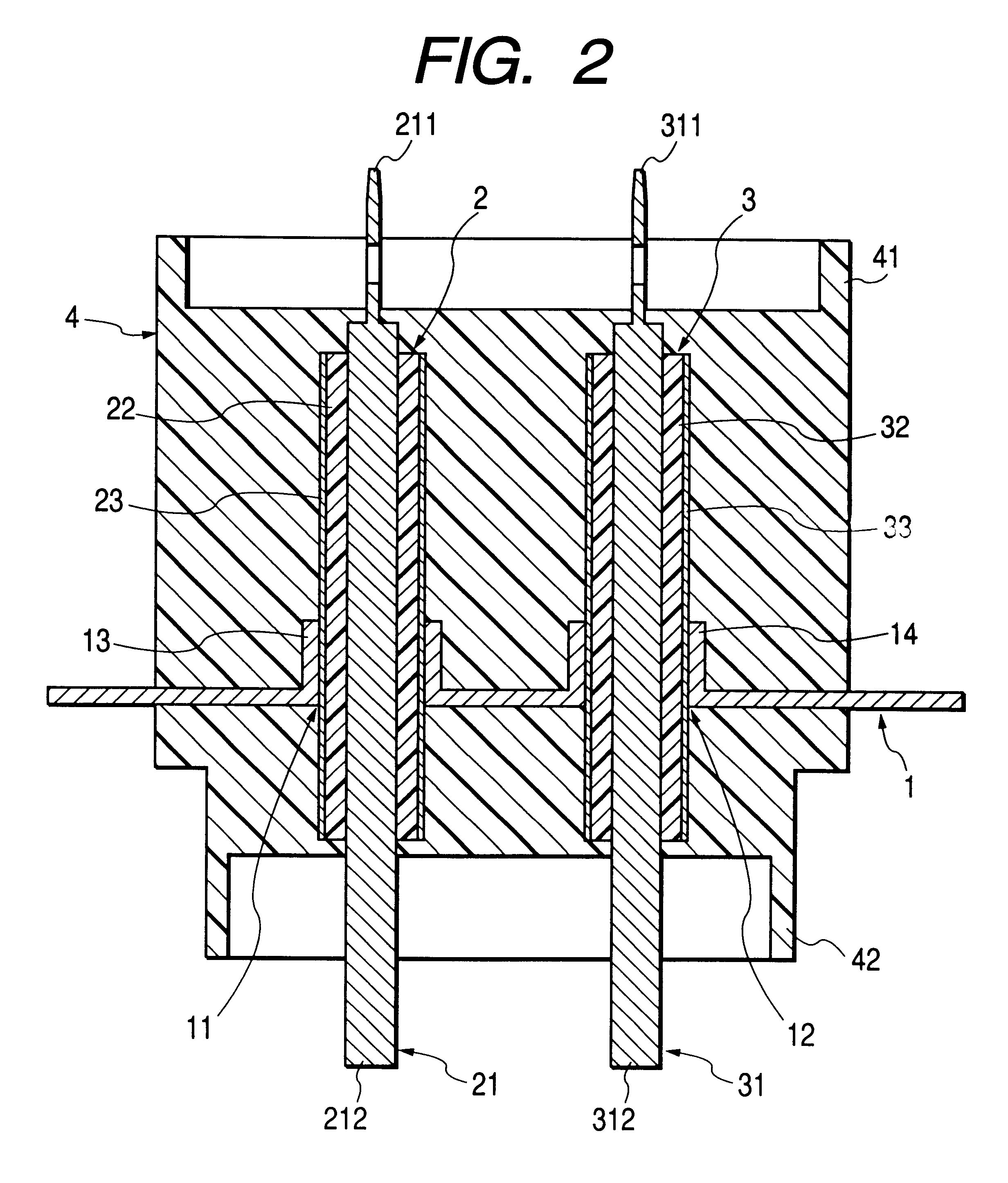
FIG. 1 is a perspective view of a high-voltage feedthrough capacitor according to the present invention. FIG. 2 is a sectional view taken on the line 2--2 of FIG. 1. The high-voltage feedthrough capacitor shown has a grounding member 1, two feedthrough capacitors 2, 31 and an armoring insulator 4. The grounding member 1 has two through-holes 11, 12 spaced away from each other.

The feedthrough capacitor 2 includes one central conductor 21, a dielectric layer 22, and an electrode 23. The periphery of the central conductor 21 is covered with the dielectric layer 22, and the surface of the dielectric layer 22 is covered with the electrode 23. The feedthrough capacitor 2 extends through the through-hole 11, and is fitted to the grounding member 1. The electrode 23 of the capacitor 2 is bonded to the grounding member 1 by means of, e.g., soldering or contact bonding o...


PUM


Abstract

In a high-voltage feedthrough capacitor, a grounding member has two through-holes spaced away from each other. Feedthrough capacitors each has one central conductor, a dielectric layer, and an electrode. The periphery of the central conductor is respectively covered with the dielectric layer, and the surface of the dielectric layer is respectively covered with the electrode. The feedthrough capacitor extends respectively through the through-hole, and has been fitted to the grounding member. The electrode has been bonded to the grounding member. An armoring insulator covers the peripheries of the feedthrough capacitors and the periphery of the grounding member.

Description

1. Field of the InventionThe present invention relates to a high-voltage feedthrough capacitor for use, e.g., in a magnetron for an microwave oven for the prevention of undesired radiation noise.2. Description of the Related ArtVarious high-voltage feedthrough capacitors of this kind have been proposed and put to practical use. For example, Examined Japanese Utility Model Publication No. Hei. 7-15129 discloses a high-voltage feedthrough capacitor which employs a central conductor constituted of simple parallel flat plates wherein a longitudinally central part thereof serves as an electrode for the central conductor, and which has an electrode part facing the electrode for the central conductor and formed by processing part of a grounding plate. In this capacitor, the dielectric member disposed between the pair of electrodes is a thermosetting resin casting united with the electrodes and serving also as a filler. This dielectric member is molded by injection molding.One problem of th...

Claims


Application Information

Patent Timeline
Patent Type & Authority Patents(United States)
IPC IPC(8): H01G4/35H01J23/15H01J23/00
CPCH01G4/35H01G2/22
Inventor SATOU, TUKASAFUJIWARA, ISAOSASAKI, SETSUO
Owner TDK CORPARATION
Why Eureka
Try Eureka