Circuit and method for writing to a memory disk with a boosted voltage

a memory disk and boosted voltage technology, applied in pulse generators, instruments, pulse techniques, etc., can solve problems such as reducing the effective rate at which data can be accurately written and read, difficulty in distinguishing successive magnetic transitions, and errors in reading data contained on the disk

Inactive Publication Date: 2003-01-28
STMICROELECTRONICS SRL
View PDF7 Cites 27 Cited by
  • Summary
  • Abstract
  • Description
  • Claims
  • Application Information

AI Technical Summary

Problems solved by technology

Since the disk is moving relative to the head, it can be seen that if the small space separating the magnetic domain transitions is not sufficiently wide, difficulty may be encountered in distinguishing successive magnetic transitions.
This may result in errors in reading the data contained on the disk, which is, of course, undesirable.
However, since the data signals are in the form of square wave transitions, if the rise time of the leading edges of the square waves is large, the small space between magnetic media transitions also becomes large, which reduces the effective rate at which data can be accurately written and read.
Since the write head assembly includes at least one coil, forcing the current to rise rapidly, or to reverse flux directions within the write head is difficult.
However, as mentioned, as data rates increase, the rates at which the heads can accurately write the data to the magnetic media is limited by the speed at which the flux in the coil 19 (and its associated components) can be reversed.
The bootstrap circuit causes the voltage appearing across the write head to relatively quickly become substantially large, thereby causing a relatively large amount of current to pass through the write head.

Method used


Image

  • Circuit and method for writing to a memory disk with a boosted voltage
  • Circuit and method for writing to a memory disk with a boosted voltage
  • Circuit and method for writing to a memory disk with a boosted voltage

Examples


Embodiment Construction

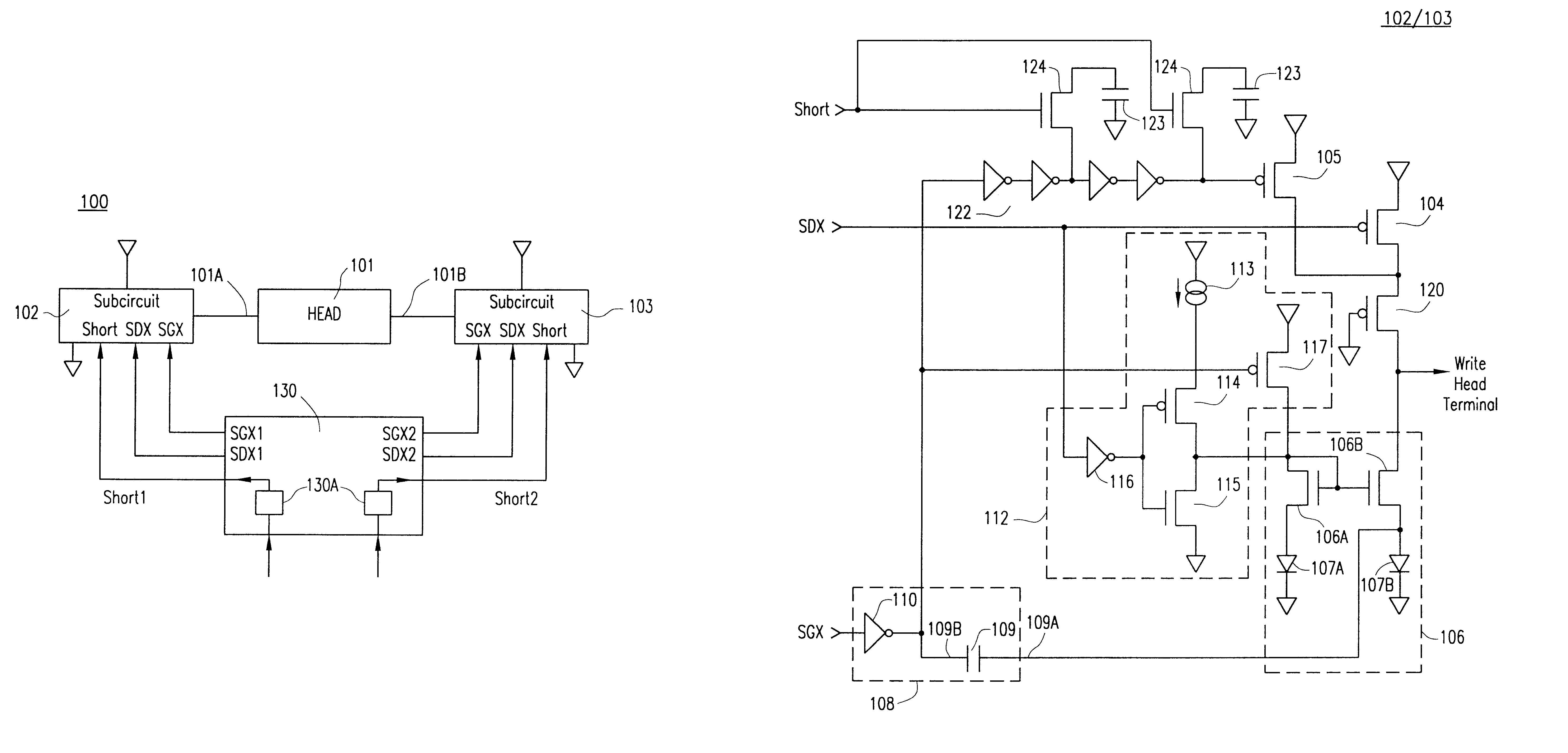
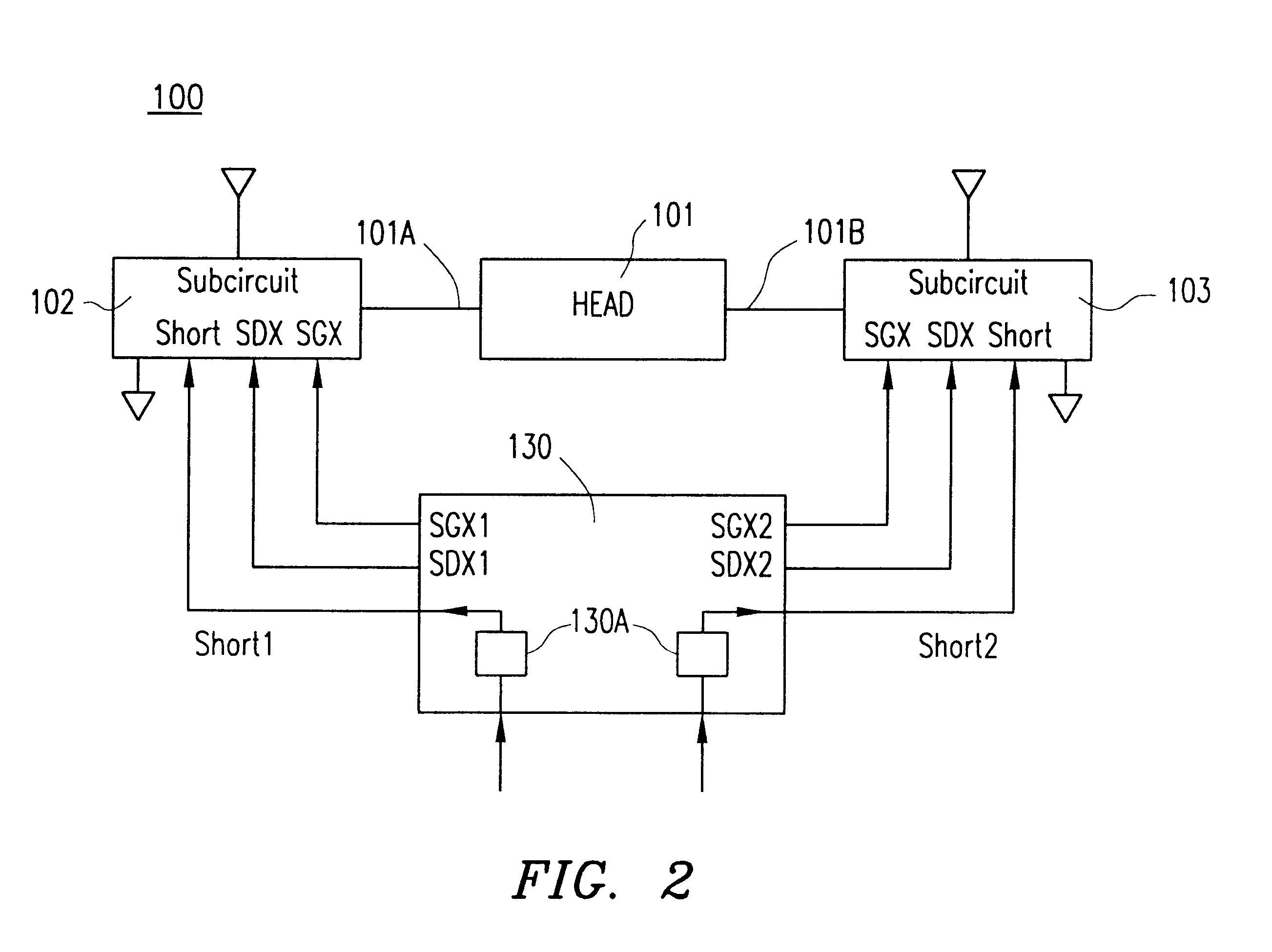
Referring to FIG. 2, there is shown a driver circuit 100 for driving the write head 101 of a magnetic disk storage device. Driver circuit 100 is implemented as an H-bridge circuit wherein current is provided to write head 101 through selected legs of driver circuit 100 for writing data onto an associated magnetic storage disk.

Driver circuit 100 includes a pair of identical sub-circuits 102 and 103, each of which is associated with a distinct terminal of write head 101. Sub-circuit 102 supplies a current to and sinks a current from write head 101 through terminal 101A thereof. Similarly, sub-circuit 103 supplies a current to and sinks a current from write head 101 through terminal 101B thereof. In this way, simultaneously controlling sub-circuits 102 and 103 provides a current through write head 101 having the desired current level and direction.

Sub-circuit 102 of driver circuit 100 (FIG. 3) includes a pull-up device connected between terminal 101A of write head 101 and a high voltag...


PUM

PropertyMeasurementUnit
voltageaaaaaaaaaa
currentaaaaaaaaaa
voltageaaaaaaaaaa

Abstract

A method and circuit are disclosed for controlling the write head of a magnetic disk storage device. The circuit includes a pull-up device coupled to a terminal of the write head, a current sink circuit which is coupled to the write head terminal and a bootstrap circuit coupled to the current sink circuit. When reversing the direction of current flow through the write head so that current is drawn from the write head from the write head terminal, the bootstrap circuit and the current sink circuit are activated. When the current in the write head nears and/or slightly surpasses the desired destination current level, the bootstrap circuit is deactivated and the pull-up device is thereafter immediately activated for a predetermined period of time.

Description

1. Technical Field of the InventionThe present invention relates to circuit and method for writing to a memory disk, and particularly to a circuit and method for driving the write head of a disk drive device.2. Background of the InventionMost computer systems include one or more associated disk drives, which may be built into or external to the computer system. Typically, disk drives have at least one rotating magnetic medium and associated head mechanisms that are carried adjacent the magnetic material. The heads are radially positionable to selectively write information to, or read information from, precise positions on the disk medium. Such disk drives may be, for example, hard disk drives, floppy drives, or the like.Data is written to the associated data disk by applying a series of signals to a write head according to the digital information to be stored on the magnetic disk media. The write head has a coil and one or more associated pole pieces that are located in close proxim...

Claims


Application Information

Patent Timeline
Patent Type & Authority Patents(United States)
IPC IPC(8): G11B5/012G11B5/02G11B5/09
CPCG11B5/012G11B5/022G11B5/02G11B5/09
Inventor PATTI, GIUSEPPEALINI, ROBERTOPAKRISWAMY, ELANGO
Owner STMICROELECTRONICS SRL
Why Eureka
Try Eureka